LH & RH Motion Control Assembly Removal (continued)
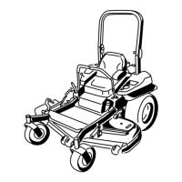
g421549
Figure 106
LH & RH Control Assembly Installation
1. Install the LH & RH motion control assemblies. Using a 9/16 inch wrench and
3/4 inch socket, install the (3/8 inch) lock nut and (1/2 inch) shoulder bolt to
secure the LH & RH motion control assemblies to the chassis.
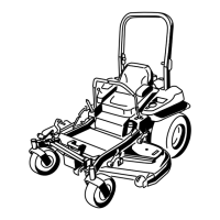
g421549
Figure 107
2. Using a 1/2 inch socket, install the (5/16 inch) bolt to secure the LH & RH
motion control dampeners to the chassis. T orque to 10 ± 1 N•m (90 ± 10
in-lb).
Drive: Service and Repairs Page 7–8 2000 Series Z MASTER®Service Manual
3460-328 Rev A

 Loading...


