32RCA001TS-02ISEN
14
RBP-RC001-E Installation & Owner's Manual
Group remote controller overview
Overview
The group remote controller (hereinafter referred to as GR) is a compact group controller that connects the following heat
source equipment and instructs the distribution of the water system of the heat source equipment, operation mode, set
temperature, and start / stop.
Heat source equipment that can be connected to GR (Note)
USX, EDGE series Heat Recovery CAONS Series 1, 2 SFMC Series 4, 5
CAONS700
[In the case of Universal Smart X (USX and EDGE Series), CAONS700, and Super Flex Modular Chiller (SFMC Series
4, 5)]
The GR can connect up to two module controllers (hereinafter referred to as MC). By connecting up to 16 unit controllers
(hereinafter referred to as UC) to each MC, up to 32 UCs can be controlled.
And you can control up to 4 water systems. The UC can be distributed and controlled for each water system. (Up to 2 water
systems can be controlled for each MC. A UC extending over MCs can be set as part of the same system and be controlled.)
Each MC detects the required flow rate on the load side according to the GR operation instructions, and instructs each UC to
start / stop the built-in inverter pump and the required flow rate or required operating frequency. (For SFMC, USX, EDGE series)
It also controls rotation to equalize the operating time of each UC.
Upon receiving the operation instruction from the MC, the UC controls the number and frequency of compressors so that the
outlet water temperature approaches the set temperature. The UC then performs rotation control to equalize the operating time
of each compressor.
USX connection example and setting example
Note : The connected models cannot be mixed in the same water system. Also, when connecting a model other than the USX
and EDGE series, it is necessary to set the model of the DN code. Refer to the DN code list (P. 51) for model settings.
Digital input
Run/Stop input, Operating pattern input, etc
Digital output
Run output, Alarm output, Operating pattern output, etc
MC1
Communication line
(RS-485)
MC2
UC (Up to 16 units)
• • •
• • •
System 1 System 2
System 2 System 3
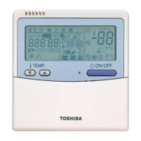
Group Remote Controller (GR)
POWER
RUN
ALARM
POWER
RUN
ALARM
 Loading...