TRANSPORTATION AND INSTALLATION MANUAL
The cables are connector-connected at the upper side of the arm 2 cover. The wiring
panel on the upper side of the same cover can also be mounted on the lower side of
the arm 2. The following three (3) manners are available for the tool wiring and
piping.
• Wiring and piping to the tool through a hollow hole (18 mm-dia.) on the tool shaft.
• Wiring and piping, using fixed stays.
• Direct wiring and piping by relocating the wiring panel to the lower side.
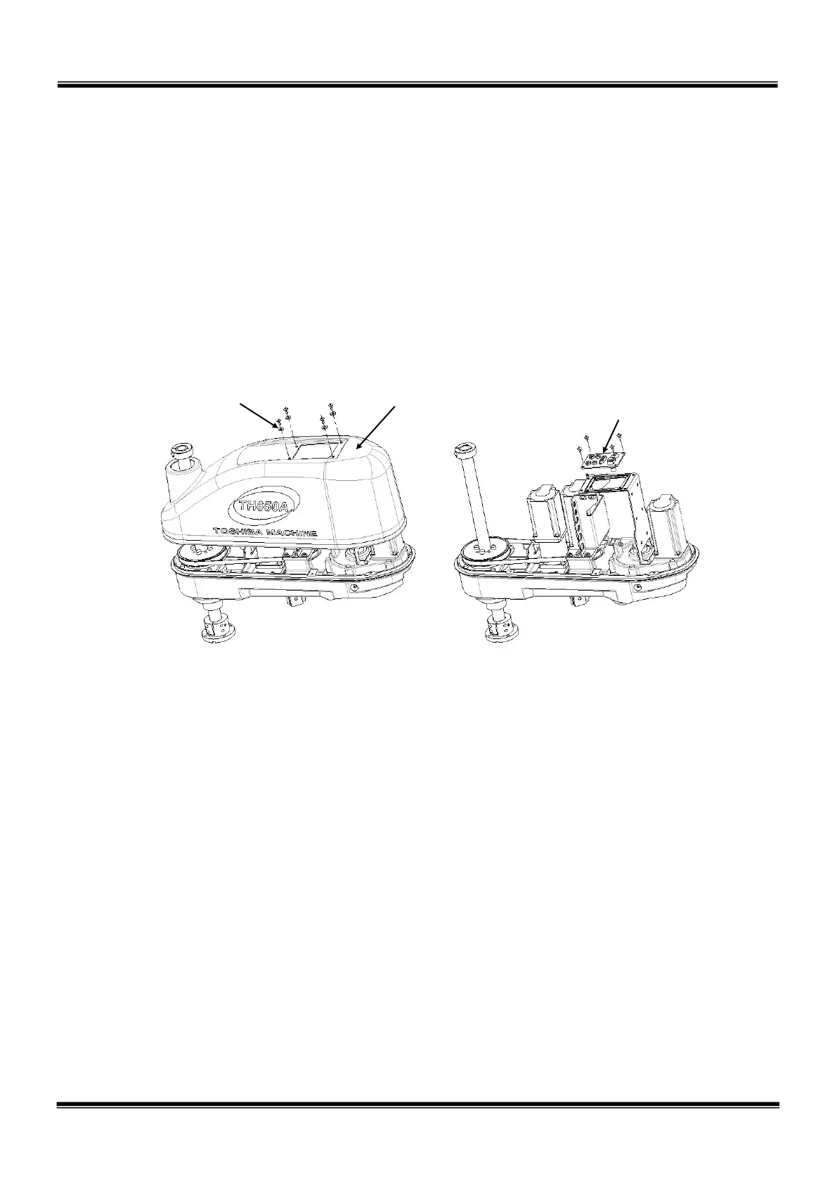
Fig. 5.5 and Fig. 5.6 show the procedures for relocating the wiring panel and the wiring
method, respectively.
1. Remove the four (4) screws securing
the cover, then draw it upward and
disconnect.
2. Remove the four (4) screws securing
the wiring panel, then dismount the
wiring panel. As all cables are
connector-connected, disconnect all
cables connected there. The gasket
for the panel should remain attached
to the steel plate securing the cover.
Connectors to be removed in Step 2:
JOEP, JOFP, JOES, JOFS
Brake OFF switch cable, four (4) air
tubes
STE 85305
– 58 –

 Loading...


