E6581595
F-33
6
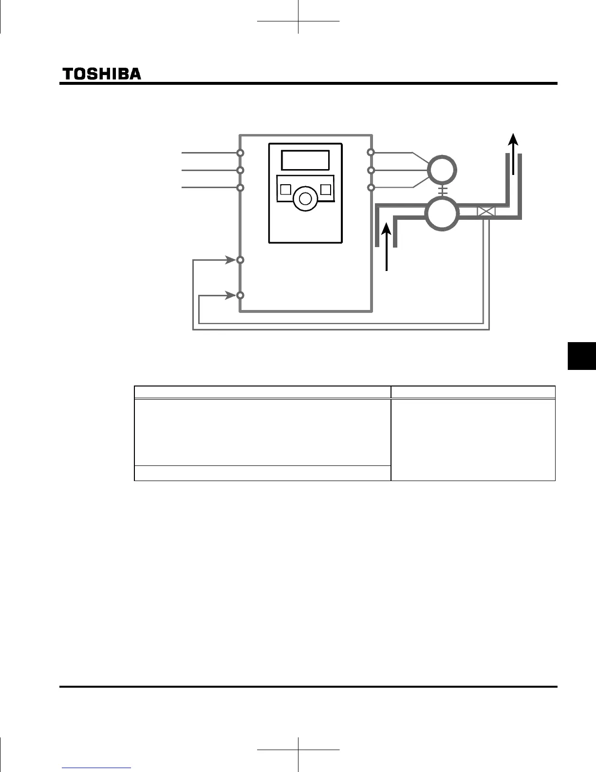
1) Example of External connection
2) Selecting PID set value and feedback value
PID set value (frequency) and feedback value can be combined as follows for the PID control.
①PID set value ②Feedback value
Frequency setup mode selection: Note 1
1: Setting dial 1 (press in center to save)
2: Setting dial 2 (save even if power is off)
3: RS485 communication
5: UP/DOWN from external logic input
Analog/logic input Selection
(VI terminal): f109 Note 2
0: Voltage signal input (0-10V)
1: Current signal input (4-20mA)
3: Voltage signal input (0-5V)
Preset-speed operation (, are all possible)
Note 1: Do not set (Terminal VI).
Note 2: Do not set (Logic input).
3) Setting PID control
Set : PID control=1(Enabled)
(1) Set : Acceleration time and : Deceleration time to the system fitting values.
(2) To limit the output frequency, set parameters : Upper limit frequency and : Lower limit frequency.
If PID set value are set with the setting dial, however, the process quantity setting range will be limited by
the settings of and .
Note 3: Assigning the terminal function number 36 (PID control prohibition) to an input terminal. PID control
function is stopped temporarily while the terminal is ON.
M
P
R/L1
S/L2
T/L3
U/T1
V/T2
W/T3
VI
CC
Pressure
transmitter
(1) Panel setting
(2) Internal preset-speed
setting
Feedback signals (1)DC : 4~20mA (2)DC : 0~10V (3)DC : 0~5V
(1) Panel keypad setting
Inverter
Motor
Pump
①PID set value setting
Setting dial
Pressure
transmitter
②Feedback value: Current signal input (4-20mA)

 Loading...


