EasyManuals Logo

Toshiba TOSVERT VF-nC3 User Manual

Toshiba TOSVERT VF-nC3
254 pages
To Next Page IconTo Next Page
To Previous Page IconTo Previous Page
Page #181 background imageLoading...
Page #181 background image
E6581595
G-6
7
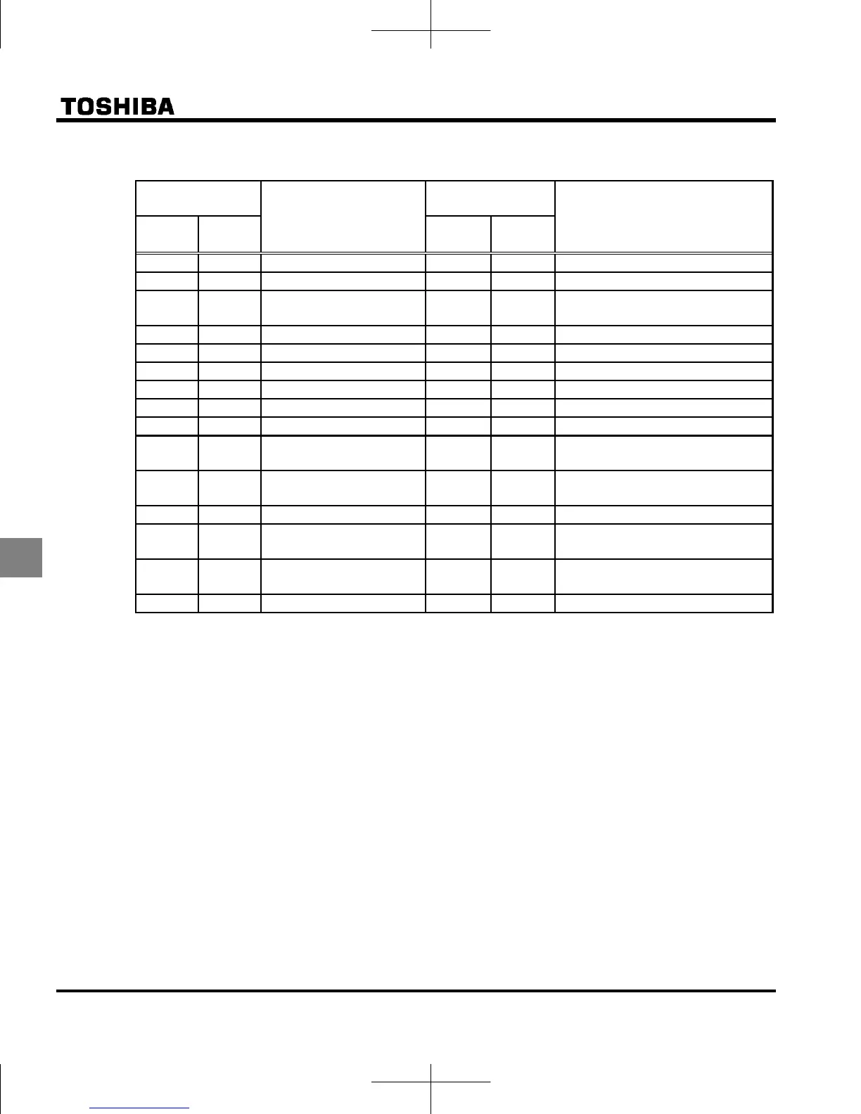
List of logic input terminal function settings
Parameter
programmed value
Function
Parameter
programmed value
Function
Positive
logic
Negative
logic
Positive
logic
Negative
logic
 No function   PID control prohibition
 Forward run command   Forced local from communication
 Reverse run command   Operation hold (hold of 3-wire
operation)
 Standby   PID integral/differential clear
 Reset command   PID characteristics switching
  Preset-speed command 1   Frequency UP *1
  Preset-speed command 2   Frequency DOWN *1
  Preset-speed command 3   Clear frequency UP/DOWN *1
  Preset-speed command 4   Coast stop command
  Jog run mode   Frequency setting mode terminal
board VI
  Emergency stop by
external signal
  Command mode terminal board
  DC braking command   Parameter editing permission
  2nd
acceleration/deceleration
  Forced deceleration command
  2nd V/F control mode
switching
  Parameter editing prohibition
  2nd stall prevention level 
*1: Active when  (frequency setting mode selection) = (UP/DOWN from external logic input) is set.
The frequency setup range is from  to  (upper limit frequency). The acceleration/deceleration time
relative to the set frequency is / while the acceleration/deceleration speed is not switched.
Refer to section 11.6 for details about the input terminal function.

Table of Contents

Other manuals for Toshiba TOSVERT VF-nC3

Questions and Answers:

Question and Answer IconNeed help?

Do you have a question about the Toshiba TOSVERT VF-nC3 and is the answer not in the manual?

Toshiba TOSVERT VF-nC3 Specifications

General IconGeneral
ModelVF-nC3
CategoryInverter
Output Frequency Range0.1 to 400 Hz
Control MethodV/f control, sensorless vector control
Overload Capacity150% for 60 seconds
Input Frequency50/60 Hz
Enclosure RatingIP20
Input Voltage200-240V AC
Protection FeaturesOvercurrent, Overvoltage, Undervoltage, Overheat, Short Circuit
Ambient Temperature-10°C to +50°C
CommunicationModbus RTU
Cooling MethodFan Cooled
Operating Temperature-10°C to +50°C
Storage Temperature-20°C to +60°C
Humidity5 to 95% RH (non-condensing)
AltitudeUp to 1000m
Braking UnitBuilt-in braking transistor (for models up to 22kW), External braking resistor required

Related product manuals