E6581595
H-9
8
Input voltage: The voltage displayed is the voltage determined by converting the voltage
measured in the DC section into an AC voltage. The reference value
(100% value) is 200 volts for 240V models, 100 volts for 120V models.
The unit can be switched to V (volts).
Output voltage: The voltage displayed is the output command voltage. 100% reference
value is 200V on both 120V and 240V models.
This unit can be switched to V (volts).
Torque current: The reference value (100% value) is the rated output current indicated on
the nameplate. The current required to generate torque is calculated from
the load current by vector operations. The value thus calculated is
displayed.
Load factor of inverter: Depending on the PWM carrier frequency (f300) setting and so on, the
actual rated current may become smaller than the rated output current
indicated on the nameplate. With the actual rated current at that time (after
a reduction) as 100%, the proportion of the load current to the rated
current is indicated in percent. The load factor is also used to calculate the
conditions for overload trip ().
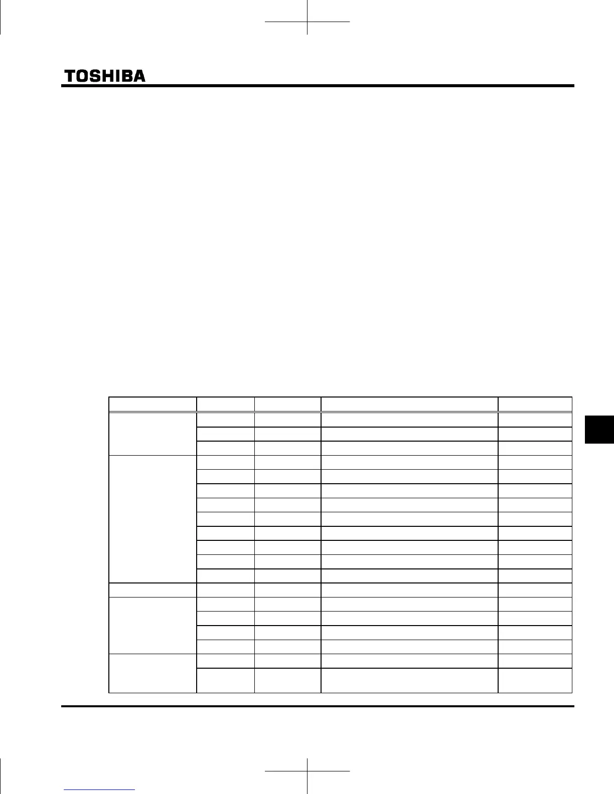
Note 11: Status monitor of * mark is displayed by to and setting.
The left side character is as following table by each parameter setting number.
Parameter Setting No. LED display Function Unit
to ,
0
x60.0
Output frequency Hz / free unit
1
c16.5
Output current % / A
2
f50.0
Frequency command value Hz / free unit
to
3
y100
Input voltage (DC detection) % / V
4
p 90
Output voltage (command value) % / V
5
k 3.0
Input power kW
6
h 2.8
Output power kW
7
q 80
Torqu e %
8
w 90
Torque current % / A
9-11 - - -
12
b51.0
Stator frequency
Hz / free unit
13-17 - - -
,
18 **** Arbitrary code from communication -
to
19-22 - - -
23
d40.0
PID feedback value Hz / free unit
24-26 - - -
27
l 70
Drive load factor %
to ,
28-51 - - -
52
w50.0
During stop : Frequency command value
During operation : Output frequency
Hz / free unit

 Loading...


