E6581595
I-3
9
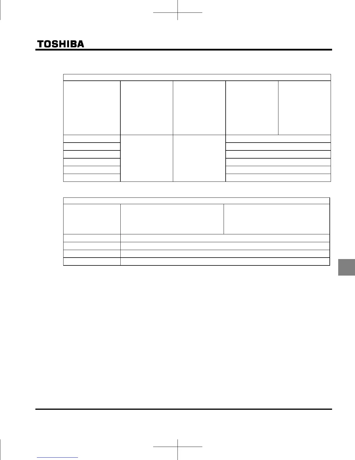
Single-phase 240 V class
Combination of inverter and filter
Inverter type
Transmission noise
IEC61800-3,
category C1
applicable filters
(motor wiring
length of less than
5 m)
Transmission noise
IEC61800-3,
category C2
applicable filters
(motor wiring
length of less
than 10 m)
Transmission noise
IEC61800-3
Category C1
Applicable filters
(Length of motor
connecting cable:
Max. 20 m, PWM
carrier frequency :
4 to 12kHz)
Transmission noise
IEC61800-3
Category C2
Applicable filters
(Length of motor
connecting cable:
Max. 50 m, PWM
carrier frequency :
4 to 12kHz)
VFNC3S-2001PL
Built-in filter Built-in filter
EMFAS2011Z
VFNC3S-2002PL EMFAS2011Z
VFNC3S-2004PL EMFAS2011Z
VFNC3S-2007PL EMFAS2011Z
VFNC3S-2015PL EMFAS2025Z
VFNC3S-2022PL EMFAS2025Z
Single-phase 120 V class
Combination of inverter and filter
Inverter type
Transmission noise
IEC61800-3 Category C1
Applicable filters
(Length of motor connecting cable: Max.
5 m, PWM carrier frequency : 4 to 12kHz)
Transmission noise
IEC61800-3 Category C2
Applicable filters
(Length of motor connecting cable: Max.
20 m, PWM carrier frequency : 4 to 12kHz)
VFNC3S-1001P EMFAS2011Z
VFNC3S-1002P EMFAS2011Z
VFNC3S-1004P EMFAS2011Z
VFNC3S-1007P EMFAS2025Z
(2) Use shielded power cables, such as inverter output cables, and shielded control cables. Route the cables
and wires so as to minimize their lengths. Keep a distance between the power cable and the control cable
and between the input and output wires of the power cable. Do not route them in parallel or bind them
together, instead cross at right angle.
(3) It is more effective in limiting the radiation noise to install the inverter in a sealed steel cabinet. Using wires
as thick and short as possible, earth the metal plate and the control panel securely with a distance kept
between the earth cable and the power cable.
(4) Route the input and output wires apart from each other.
(5) To suppress radiation noise from cables, ground all shielded cables through a noise cut plate.
It is effective to earth shielded cables in the vicinity of the inverter and cabinet (within a radius of 10cm from
each of them). Inserting a ferrite core in a shielded cable is even more effective in limiting the radiation
noise.
(6) To further limit the radiation noise, insert a zero-phase reactor in the inverter output line and insert ferrite
cores in the earth cables of the metal plate and cabinet.

 Loading...


