E6581595
A-21
1
How to install
Warning
Prohibited
Do not install or operate the inverter if it is damaged or any component is missing.
This can result in electric shock or fire. Contact your Toshiba distributor for repairs.
Mandatory
action
Mount the inverter on a metal plate.
The rear panel gets very hot. Do not install in an inflammable object, this can result in fire.
Do not operate with the front panel cover removed.
This can result in electric shock.
An emergency stop device must be installed that fits with system specifications (e.g. shut off input
power then engage mechanical brake).
Operation cannot be stopped immediately by the inverter alone, thus risking an accident or injury.
All options used must be those specified by Toshiba.
The use of any other option may result in an accident.
Caution
Mandatory
action
The main unit must be installed on a base that can bear the unit's weight.
If the unit is installed on a base that cannot withstand that weight, the unit may fall resulting in injury.
If braking is necessary (to hold motor shaft), install a mechanical brake.
The brake on the inverter will not function as a mechanical hold, and if used for that purpose, injury
may result.
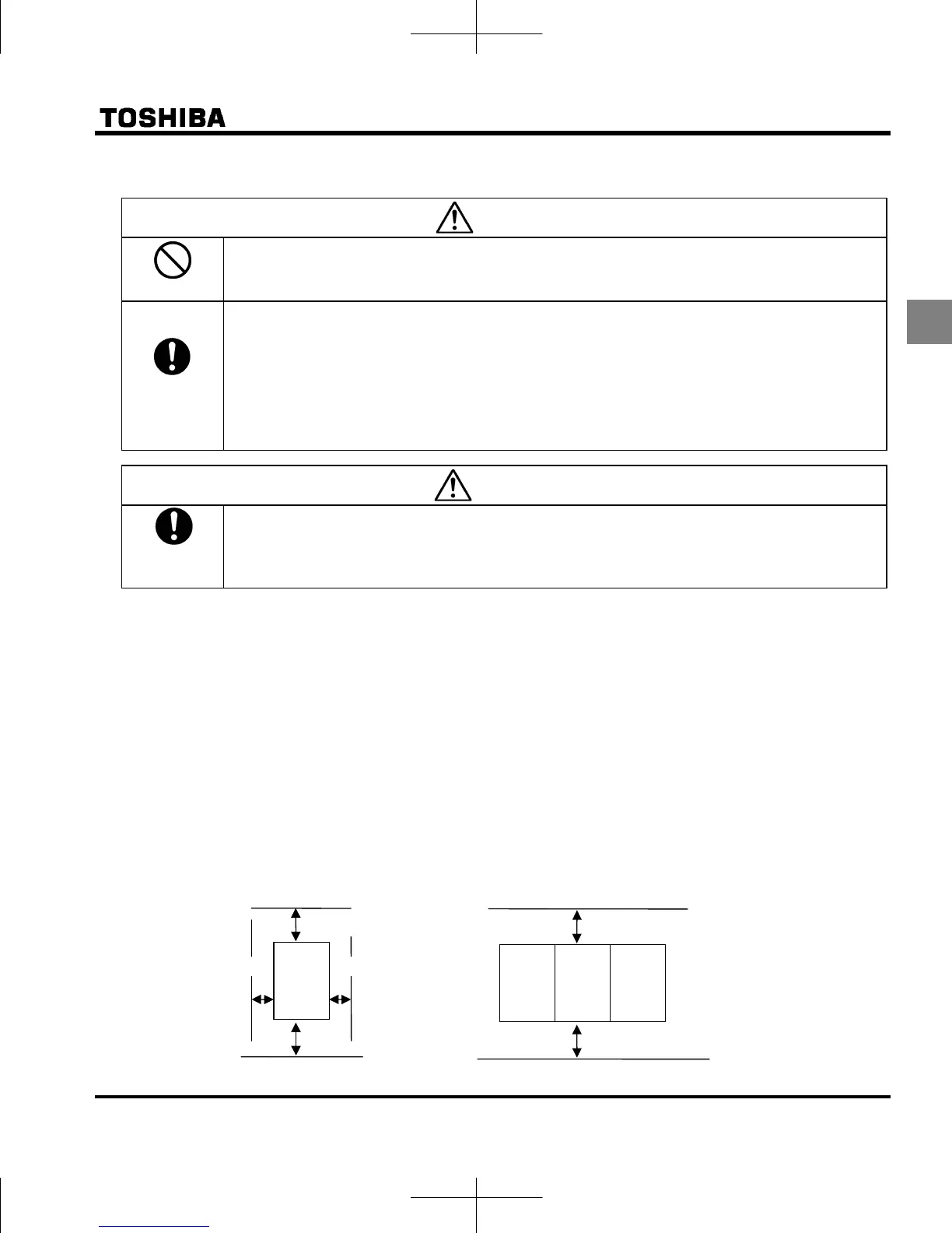
(1) Normal installation
Select an indoor location with good ventilation, and then install it upright on a flat metal plate.
When installing multiple inverters, leave at least 5 cm of space between each inverter and install them
aligned horizontally.
When using the inverter in locations with temperatures above 40°C, remove the caution plate (sticker) on top
of the inverter before use. Current reduction is necessary in locations with temperatures above 50°C.
(2) Side-by-side installation
To align the inverters side-by-side horizontally, remove the caution plate (sticker) on top of the inverter before
use. Current reduction is necessary in locations with temperatures above 40 °C.
If the door is opened 90° or more, please open the door with the left side inverter’s door open when the same
capacity inverters are installed with side-by-side.
3 cm or more
3 cm or more
5 cm or more
5 cm or more
VFnC3
Remove seals on top
VFnC3 VFnC3 VFnC3
5 cm or more
5 cm or more
Normal installation
Side-by-side installation

 Loading...


