E6581595
B-5
2
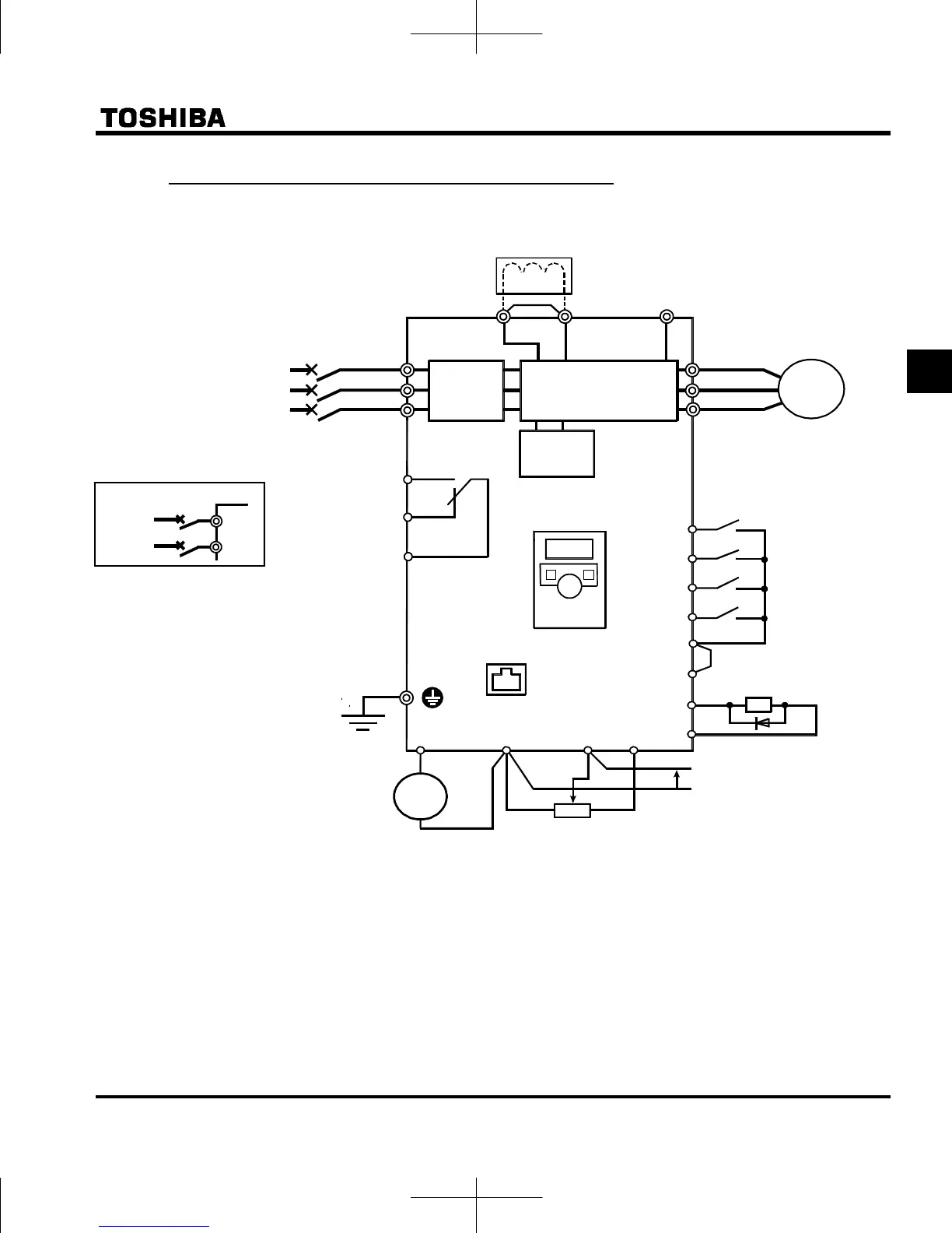
2.2.2 Standard connection diagram 2
MCCB
*1
R/L1
S/L2
T/L3
U/T1
V/T2
W/T3
Motor
NO
CC
+
+
-
-
P0
Meter
External potentiometer (1k-10k)
Control
circuit
Protective function
activation output
VF-nC3
Power circuit
*1: The T/L3 terminal is not provided for
single-phase models.
*4: 1ph-240V models have noise filter inside.
DC reactor (DCL)
Standard connection diagram - SOURCE (Positive) (common:P24)
7.5V-1mA
(or 0-10V/4-20mA)
FM
CC
VI
P5
PA/+
PC/
-
Voltage signal: 0-5V/0-10V
(Current signal: 4-20mA)
Low-Speed
signal output
Ry
*4
Use the R/L1 and S/L2 terminal as input
terminals.
*2: The inverter in supplied with the PO and
the PA/+ terminals shorted by means of
a shorting-bar.
Before installing the DC reactor (DCL),
remove the bar.
*3: When using the NO output terminal in
source logic mode, short the P24 and
OUT terminals.
Noise
filter
I M
Frequency
met er
( ammet er )
RS485
communication
connector
Operation panel
*2 , *5 (option)
*5: 1ph-120V models cannot be used with
DC reactors.
FLC
FLB
FLA
*6: When external potentiometer is connected
by using P5 terminal, set the parameter
f109=3.
*7
*6
MCCB(2P)
R/L1
S/L2/N
Power supply
Single phase
Main circuit power supply
1ph-120V class: single-phase 100-120V
-50/60Hz
1ph-240V class: single-phase 200-240V
-50/60Hz
3ph-240V class: three-phase 200-240V
-50/60Hz
*7: When VI terminal is used as a contact
input terminal, refer to page B-12.
F
R
S1
S2
OUT
Forward run command
Reverse run command
Preset-speed command 1
Preset-speed command 2
*3
P24
Common

 Loading...


