126
TK 61753-2-MM-EN
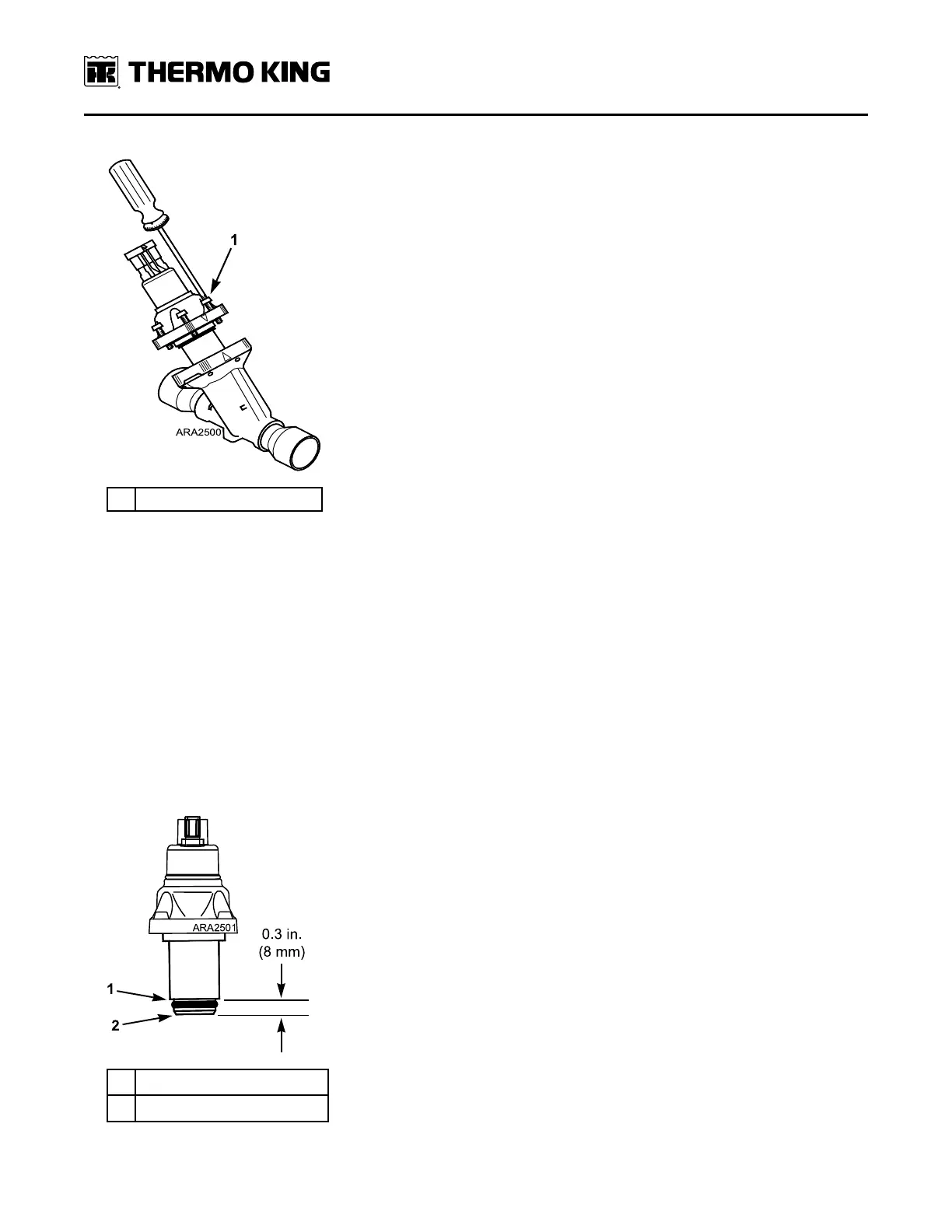
Figure 70. Removing Stepper Motor
1. Remove Four Screws
4. If the complete ETV assembly is being replaced, unsolder and remove the valve body. It may be necessary to
unsolder the tubes above or below the valve body to obtain enough clearance to remove the valve body. Note the
position of the valve body so the new one will be placed in the same position. The new ETV could interfere with
other components if it is not placed in the same position as the old one.
Installation of Service Kit
NNoottee:: Do not connect the main/unified wire harness to the ETV and turn the unit on before the stepper motor and piston
assembly is installed in the valve body. The controller is programmed to close the ETV when the unit is turned on.
If the unit is turned on with the ETV connected to main wire harness, the controller will attempt to close the ETV.
This will cause the piston to be turned (screwed) off the threaded shaft of the stepper motor because the valve
body is not present to stop it.
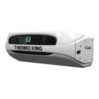
1. The new stepper motor and piston assembly is supplied with the piston in the open position. In the open position
the bottom edge of the piston is 8 to 18 mm (0.3 to 0.7 in.) from the bottom edge of the piston housing. The piston
retracts to open and extends to close.
Figure 71. Stepper Motor and Piston Assembly with Piston in Fully Open Position
1.
Bottom Edge of Piston Housing
2. Bottom Edge of Piston
RReeffrriiggeerraattiioonn SSeerrvviiccee OOppeerraattiioonnss