TK 61753-2-MM-EN
83
0 F -18 C 30.4 Amps 37.2 Amps
25 F -4 C 28.7 Amps 35.0 Amps
50 F 10 C 27.2 Amps 33.2 Amps
76 F 24 C 26.0 Amps 31.8 Amps
100 F 38 C 24.9 Amps 30.4 Amps
125 F 52 C 23.3 Amps 28.4 Amps
150 F 66 C 23.3 Amps 28.5 Amps
d. If the current is out of specifications, examine the circuit (fuses, relays, wires, etc.) for faults. If the circuit is OK,
proceed to “Fuel Solenoid Replacement” (below).
e. If the current is within specifications, proceed to step 8 for a visual check.
8. Visual functionality check (no measurements required).
CCAAUUTTIIOONN
RRiisskk ooff IInnjjuurryy!!
TThhee ffuueell ssoolleennooiidd ccaassiinngg mmaayy ggeett hhoott dduurriinngg tthhiiss rraappiidd ccyycclliinngg,, uussee ccaauuttiioonn wwhheenn hhaannddlliinngg..
a. Using the microprocessor keypad, energize the fuel solenoid circuit for 4 seconds. Turn off. Repeat ten times.
b. During each of these cycles, watch that the fuel solenoid plunger retracts completely and stays retracted until
you de-energize the circuit.
c. If the fuel solenoid plunger fails to actuate or hold during this test, check that the circuit is OK. If it appears
normal, proceed to “Fuel Solenoid Replacement” (below).
Fuel Solenoid Replacement
1. Disconnect the fuel solenoid wire connector from the main/unified wire harness and remove the old fuel solenoid.
2. Connect the new fuel solenoid wire connector to the main/unified wire harness.
3. Press the ON Key to turn the unit on.
4. Use the microprocessor keypad to enter the . Refer to the appropriate Microprocessor Diagnostic Manual for
specific information about the .
5. Perform a visual functionality check per step 8 in “Testing the Fuel Solenoid” above to verify the fuel solenoid
operates correctly.
6. Energize the fuel solenoid by energizing the run relay with the .
NNoottee:: The fuel solenoid must be energized when it is installed. If not, the plunger and the linkage may not line up
correctly and the fuel solenoid will not function properly.
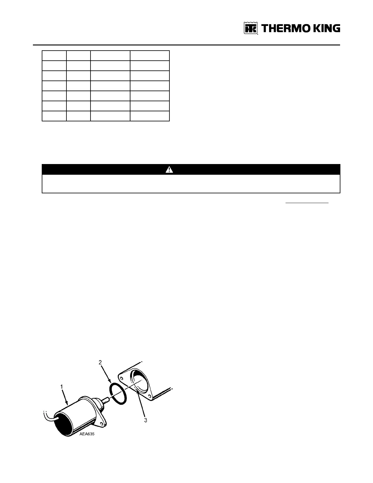
7. Place the O-ring in the groove in the end of the fuel injection pump. Make sure that the O-ring is positioned correctly
during installation to avoid damage and leaks.
Figure 37. Fuel Solenoid Components
EEnnggiinnee MMaaiinntteennaannccee