128
TK 61753-2-MM-EN
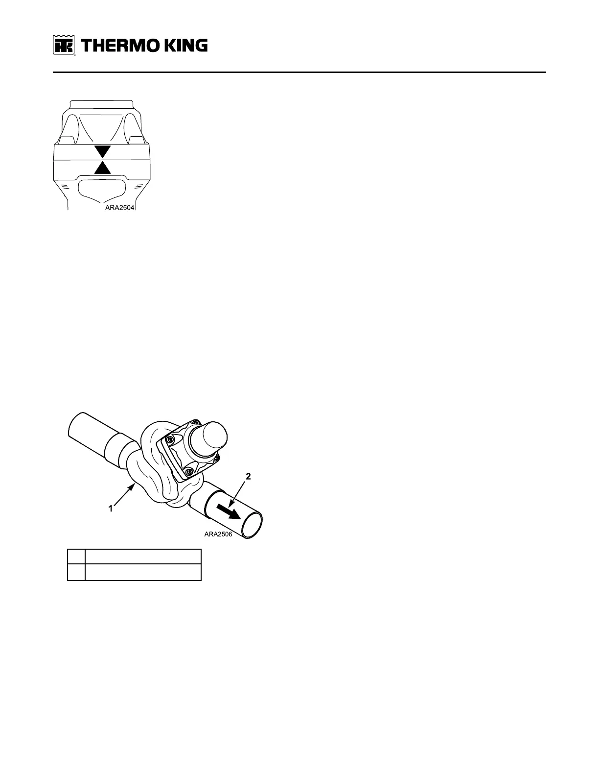
Figure 74. Align Arrowhead Marks
4. Install the four screws and torque them to 6.0 ± 0.5 N•m (4.4 ± 0.4 ft-lb).
5. Connect the main/unified wire harness to the ETV at the four-pin connector.
6. Pressurize the low side and test for leaks.
7. If no leaks are found, evacuate the low side.
8. Open the refrigeration valves and place the unit in operation.
Installation of Complete ETV Assembly
1. Clean the tubes for soldering.
2. Place the new complete ETV assembly (and any tubes that were removed) in the same position from which the old
one was removed. The new ETV could interfere with other components if it is not placed in the same position as the
old one. The ETV assembly must be installed as shown below relative to the direction of refrigerant flow from the
accumulator to the compressor.
NNoottee:: Do not disassemble the new ETV to solder it in place.
Figure 75. Installing Complete ETV Assembly
1. Use Heat Sink
2.
Direction of Refrigerant Flow
3. Use a heat sink or wrap the valve body with a wet rag to prevent damage and solder the tubing connections with
95-5 soft solder.
4. Connect the main/unified wire harness to the ETV at the four-pin connector.
5. Pressurize the low side and test for leaks.
6. If no leaks are found, evacuate the low side.
7. Install the components that were removed to access the ETV.
8. Open the refrigeration valves and place the unit in operation.
RReeffrriiggeerraattiioonn SSeerrvviiccee OOppeerraattiioonnss