84
TK 61753-2-MM-EN
1. Fuel Solenoid
2. O-ring
3. Groove in Fuel Injection Pump
8. Install the new fuel solenoid.
9. Press the OFF Key to turn the unit off after installing the fuel solenoid.
Engine Valve Clearance Adjustment
The valve clearance should be adjusted every 3,000 hours.
1. Remove the rocker arm cover.
2. Remove the round cover (plug) from the timing mark access hole on the front of the bell housing.
WWAARRNNIINNGG
RRiisskk ooff IInnjjuurryy!!
LLoooosseenn aallll ooff tthhee iinnjjeeccttiioonn lliinneess aatt tthhee iinnjjeeccttiioonn nnoozzzzlleess ttoo pprreevveenntt tthhee ppoossssiibbiilliittyy ooff tthhee eennggiinnee ffiirriinngg wwhhiillee iitt iiss
bbeeiinngg rroottaatteedd..
3. Place the engine at top dead center of the compression stroke for the number one cylinder. See steps a through d.
a. Rotate the engine in the normal direction of rotation (clockwise viewed from the water pump end) until the 1-4
timing mark on the flywheel lines up with the index mark in the timing mark access hole.
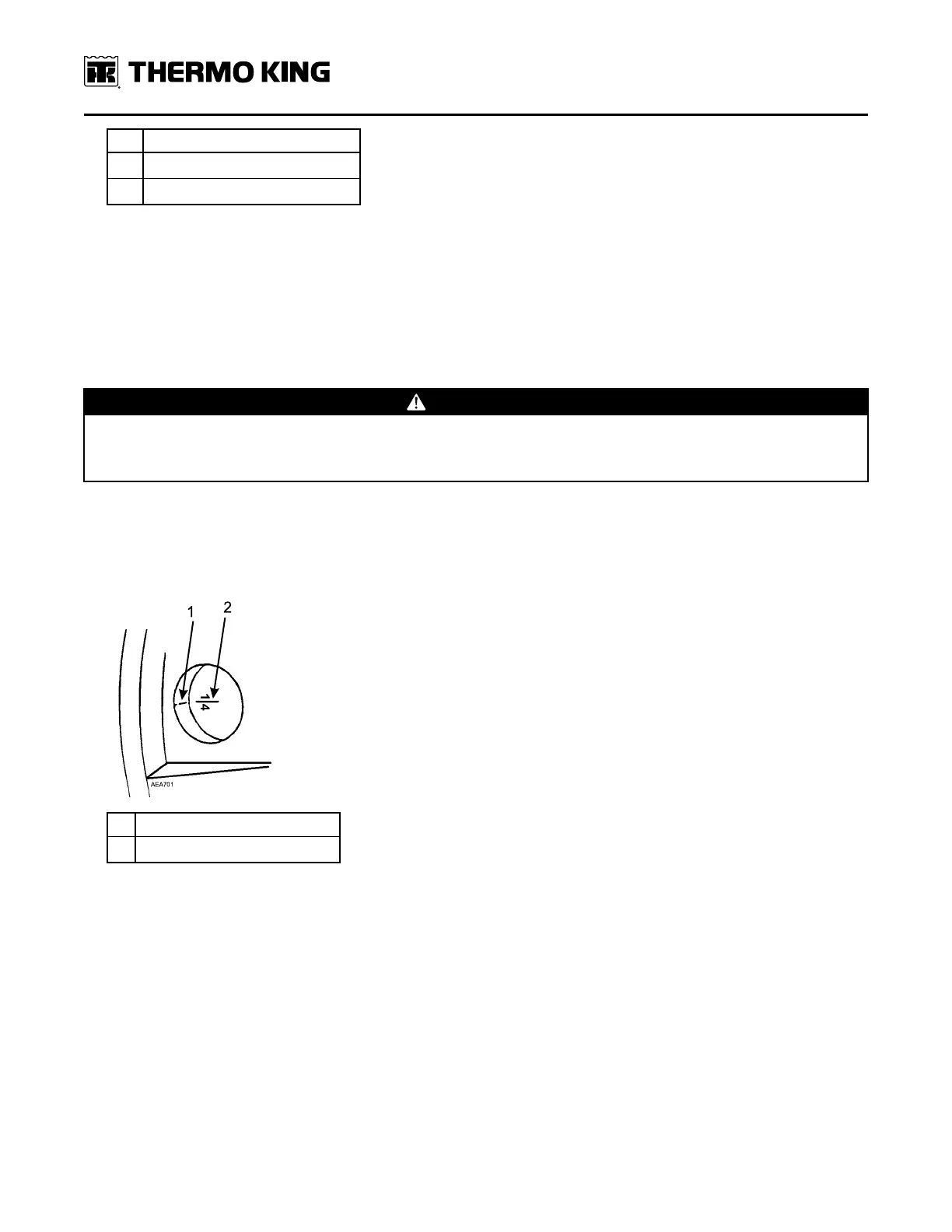
Figure 38. Top Dead Center One and Four
1. Index Mark
2. Top Dead Center Mark for 1 and 4
b. Check the rocker arms on the number one cylinder to see if they are loose.
c. If the rocker arms are loose, the engine is at top dead center of the compression stroke for the number one
cylinder.
d. If the rocker arms are tight, the engine is at top dead center of the exhaust stroke for the number one cylinder.
Rotate the engine 360 degrees to place the engine at top dead center of the compression stroke for the number
one cylinder.
4. Use a feeler gauge to check the valve clearance on both valves for the number one cylinder, the intake valve for the
number two cylinder, and the exhaust valve for the number three cylinder. The valve clearance for both the intake
valve and the exhaust valve should be 0.15 to 0.25 mm (0.006 to 0.010 in.).
a. Check to verify that the valve stem cap is in good condition and is positioned squarely on the top of the valve
stem. Replace the valve stem cap if it shows significant wear.
5. Adjust the valves if necessary by loosening the locknut and turning the adjustment screw until the valve clearance
is correct.
EEnnggiinnee MMaaiinntteennaannccee