TK 61753-2-MM-EN
79
Injection Pump Removal
The injection pump drive gear will not fit through the gear housing when removing the pump, the gear must be
separated from the pump. Using tool P/N 204-1011, it will not be necessary to remove the belts, crankshaft pulley,
crankshaft seal or front plate. See Figure 34, p. 80.
1. Note the alignment of the index marks on the injection pump and the gear case. The index mark on the injection
pump is usually aligned with the single index mark on the gear case. If not, mark it so the injection pump can be
returned to the same position when it is reinstalled.
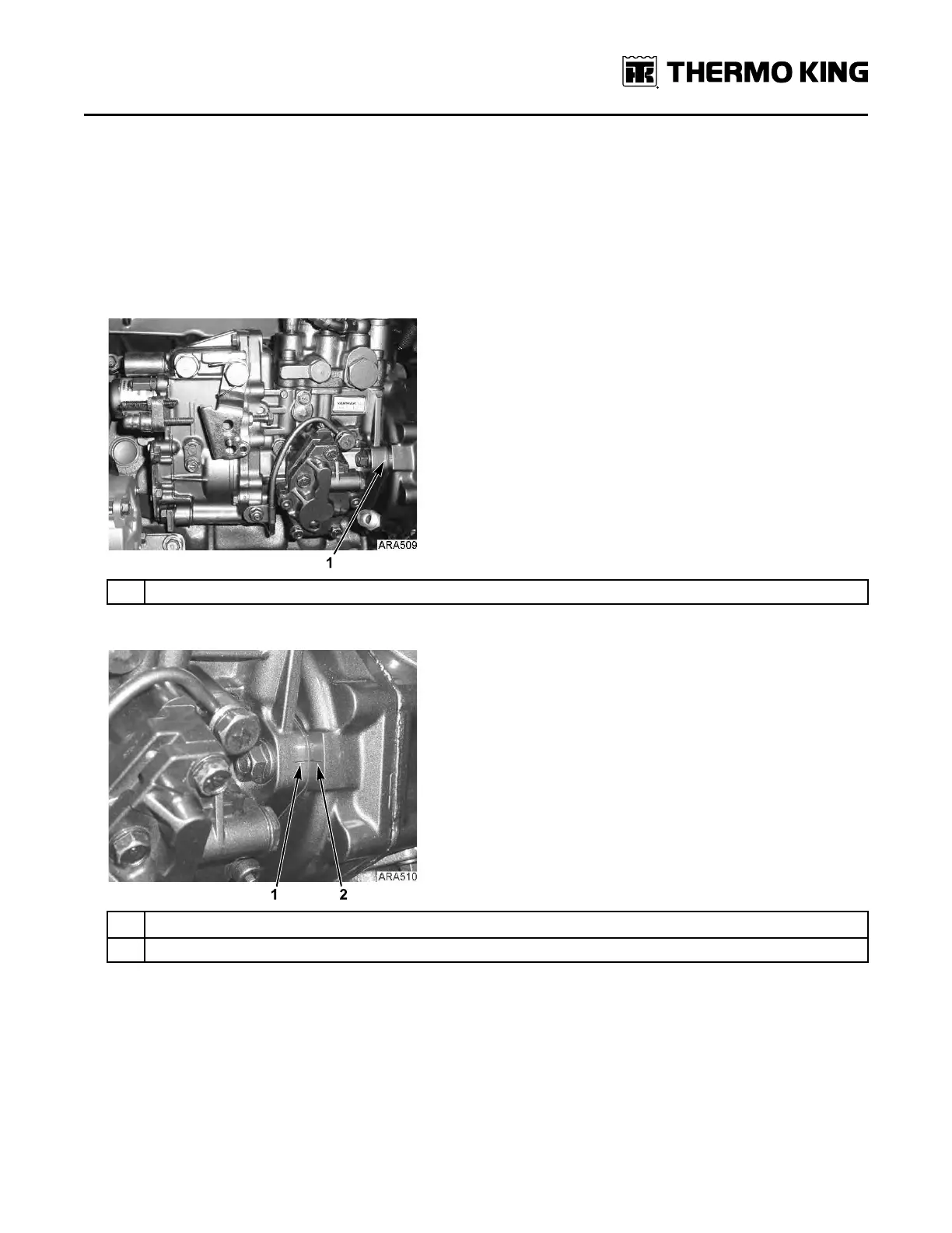
Figure 32. Index Mark Location
1.
Index Marks
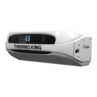
Figure 33. Index Mark Alignment
1. Index Mark on Injection Pump
2. Index Mark on Gear Case
2. Remove the starter for clearance, remove throttle linkage, fuel lines, harness and mounting hardware from injection
pump.
3. Remove the cover plate from the gear case. Remove the nut and lock washer which secure the gear to the injection
pump shaft. Use a shop rag to prevent the lock washer or nut from falling into the gear case.
NNoottee:: The injection pump gear assembly is made of three pieces; the flange, the gear, and the transfer pump cam.
Do not loosen or remove the four bolts that fasten the gear to the flange because that changes the timing.
4. Use the hardware from the cover plate to attach the tool plate (with the marked side pointing up and out) to the gear
case.
EEnnggiinnee MMaaiinntteennaannccee