TK 61753-2-MM-EN
85
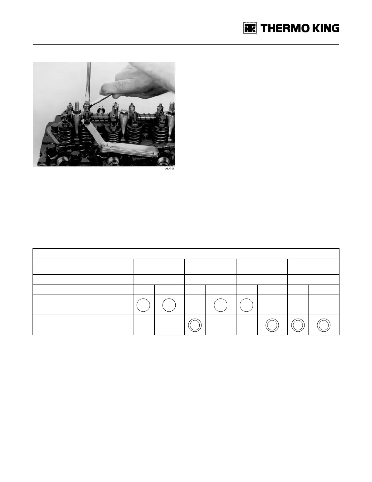
Figure 39. Adjusting the Valve Clearance
6. Hold the adjustment screw in place and tighten the locknut.
7. Recheck the valve clearance.
8. Rotate the engine one full turn (360 degrees) in the normal direction of rotation (clockwise viewed from the water
pump end), and align the 1-4 timing mark on the flywheel with the index mark in the timing mark access hole. This is
top dead center of the compression stroke for the number four cylinder.
9. Check and adjust the exhaust valve for the number two cylinder, the intake valve for the number three cylinder, and
both valves for the number four cylinder.
10. Replace the rocker arm cover, the cover for the timing mark access hole, and tighten the fuel injection lines when
finished.
Valve Adjustments and Cylinder Configurations
Rear Flywheel
End
Front Pulley End
Cylinder Number
1 2 3 4
Valve arrangement E I E I E I E I
Piston in No. 1 cylinder is at TDC on
compression stroke
Piston in No. 4 cylinder is at TDC on
compression stroke
Crankcase Breather
Gases formed in the crankcase are directed to the intake manifold. Harmful vapors that would otherwise collect in the
crankcase and contaminate the oil, or escape to the outside, are drawn back into the engine and burned.
The crankcase breather is located in the valve cover. A restrictor is cast into the fitting for the breather hose on the
intake manifold. The restrictor limits the flow of gases from the crankcase to the intake manifold and keeps the
crankcase pressure from getting too low in vacuum. A breather hose connects the crankcase breather to the intake
manifold.
EEnnggiinnee MMaaiinntteennaannccee