82
TK 61753-2-MM-EN
d. If the resistance is out of specifications, proceed to “Fuel Solenoid Replacement” (below). If the resistance is OK,
continue to step 4.
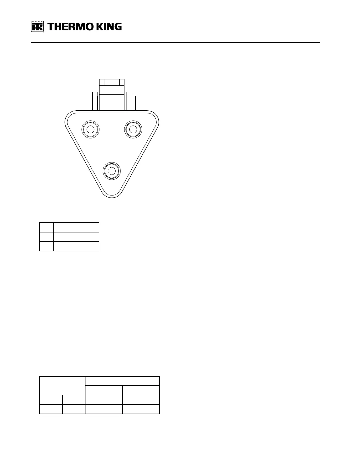
Figure 36. Fuel Solenoid Connector Pin Identification
1. Red (8D)
2.
White (8DP)
3. Black (CH)
4. Re-connect the fuel solenoid to the wire harness but do not reinstall on the engine. Leave the fuel solenoid hanging
from the wire harness so that it is in sight.
5. Connect an amp clamp on the white wire at the solenoid OR the wire labeled “8DP” on the other side of the Deutsch
connector (if it is more accessible there). If your meter is equipped, put it in “Inrush” or “Min/Max” mode so that it
records the current measured during the time that the pull coil is energized.
6. Use the microprocessor keypad to enter the . Refer to the appropriate Microprocessor Diagnostic Manual for
specific information about the .
7. Check the pull-in coil current.
a. Energize the run relay with the . Verify the pull-in coil measurement is recorded during the first two seconds the
run relay is energized.
b. IImmppoorrttaanntt:: CChheecckk tthhaatt tthhee ppuullll--iinn ccooiill aammppeerraaggee ((oonn 88DDPP)) ddrrooppss ooffff aafftteerr 22 sseeccoonnddss.. IIff tthhiiss ccooiill ccoonnttiinnuueess
ddrraawwiinngg ccuurrrreenntt ffoorr mmoorree tthhaann 33 sseeccoonnddss tthheerree iiss aa rreellaayy,, ccoonnttrroolllleerr,, oorr wwiirriinngg iissssuuee.. CChheecckk uunniitt rreeppaaiirr
hhiissttoorryy ffoorr ssiimmiillaarr iissssuueess..
c. The current through the pull-in coil should be 26 to 32 amps at 76 F (24 C).
NNoottee:: The current specifications above are for measurement at 76 F (24 C). If it is not possible to measure at
room temperature, use the following table as a guide for the expected current:
Temperature
Pull-In Coil Current
Low End High End
-25 F -32 C 31.8 Amps 38.9 Amps
-10 F -23 C 30.8 Amps 37.7 Amps
EEnnggiinnee MMaaiinntteennaannccee