Erecting a wall and creating an installation opening
Erect the shaft wall according to the manufacturer's instructions and create an installation opening with rein-
forcing strips, see Fig. 77
– Option A: Create an opening in the cladding and reinforce it along the perimeter.
– Option B: Provide the installation opening in the metal support structure with support sections. Install four
additional sections at an angle of 45° in order to reinforce the metal support structure.
Fix the cladding and reinforce the installation opening along the perimeter.
Installation opening ☐A [mm]
Installation type Nominal size Æ
nominal width
315 355 400 450 500 560 630 710 800
Mortar-based installation
1
☐A = Ænominal width + max. 450 mm
☐A1 = ☐A + (2 × trim panels)
1)
Optional trim panels
5.10.2 Mortar-based installation
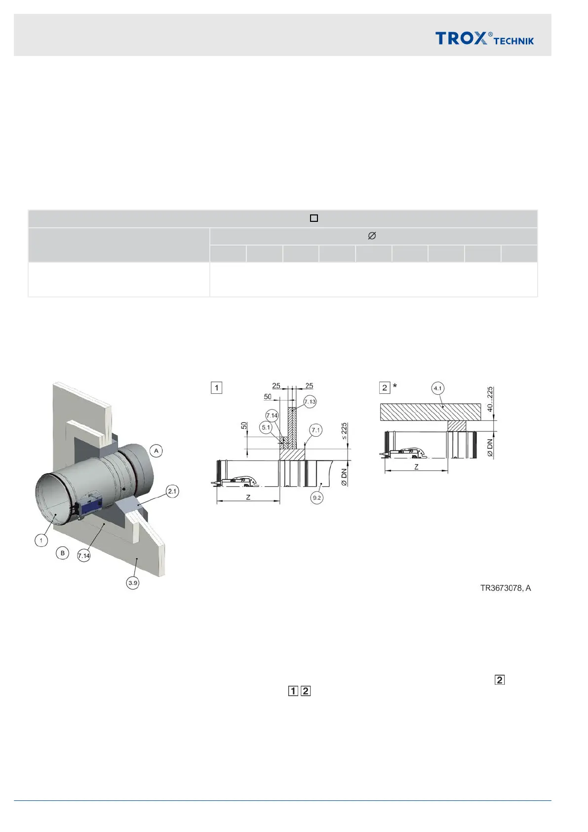
Mortar-based installation into shaft wall without metal support structure
Fig. 78: Mortar-based installation into shaft wall without metal support structure
1 FKR-EU
2.1 Mortar
3.9 Shaft wall without metal support structure, clad-
ding on one side
4.1 Solid ceiling slab / solid floor
5.1 Dry wall screw
7.1 UW section
7.13 Cladding, double layer, fire-resistant
7.14 Reinforcing board of the same material as the
wall
9.2 Extension piece or duct
Z Spigot construction 370 mm
Flange construction 342 mm
*
Installation near the floor analogous to
Up to EI 90 S
Additional requirements: mortar-based installation
into shaft walls without metal support structure
Shaft wall,
Ä
on page 35
Installation
Shaft walls without metal support structure > Mortar-based installation
Fire damper FKR-EU104