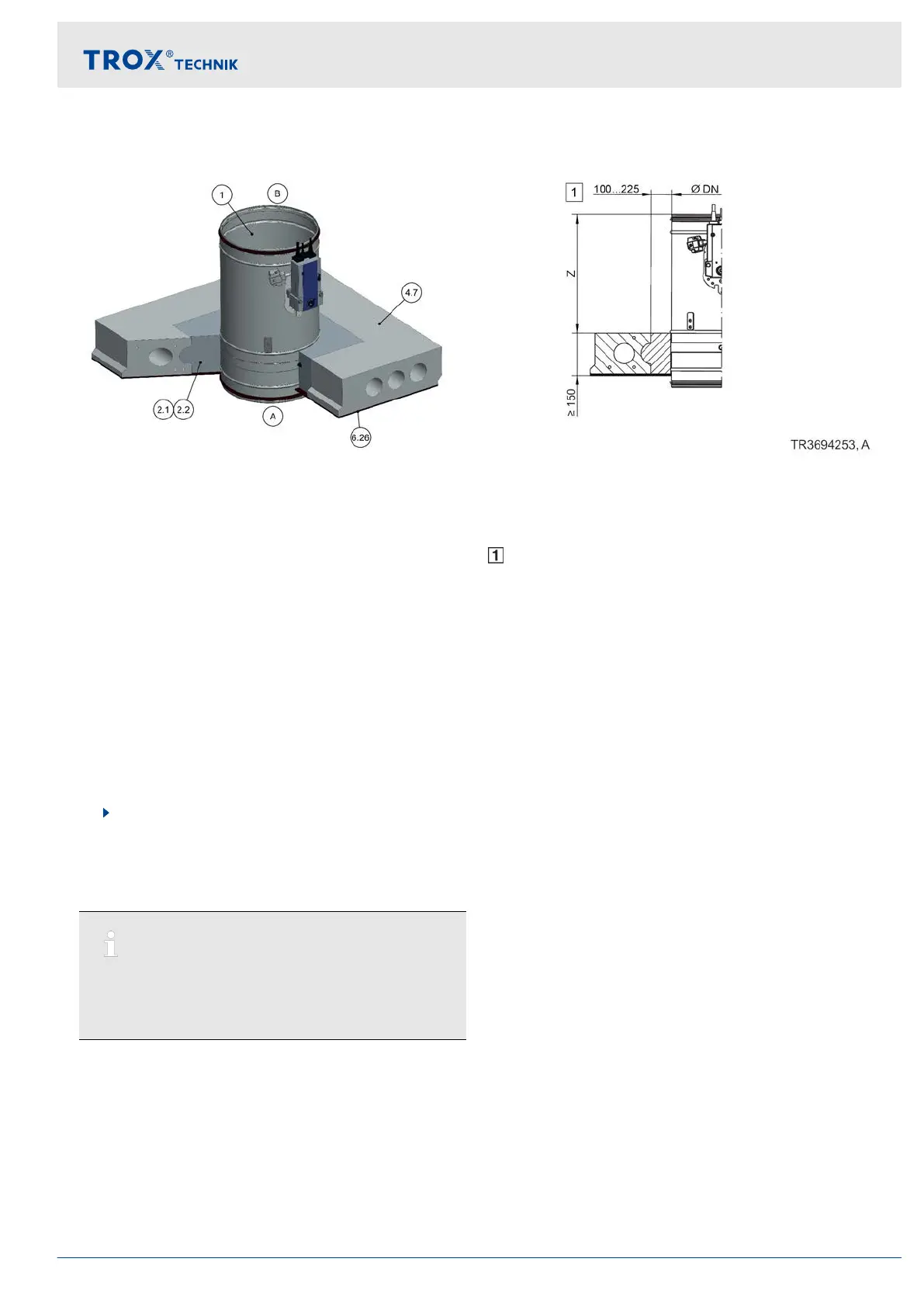
5.11.7 Mortar-based installation into hollow chamber ceilings
Fig. 92: Mortar-based installation into hollow chamber ceilings, shown upright (also applicable for suspended
arrangement)
1 FKR-EU
2.1 Mortar
2.2 Concrete
4.7 Reinforced hollow chamber ceiling*
6.26 Plaster*
Z Spigot construction 370 mm
Flange construction 342 mm
Up to EI 90 S
* Illustration representative, other ceiling construc-
tions possible according to local conditions and
ceiling manufacturers
Additional requirements: mortar-based installation
into hollow chamber ceilings
Hollow chamber ceiling,
Ä
on page 36
≥ 40 mm distance from fire damper to load-bearing
structural elements
≥ 200 mm distance between two fire dampers in
separate installation openings
After the installation opening has been created,
the adjacent open spaces must be partially closed
off all the way round (in relation to the depth) by at
least 100 mm.
Note:
Structural and fire resistance properties of the ceiling
construction, including the attachment to the con-
crete or any required reinforcement, have to be eval-
uated and ensured by others.
Installation
Solid ceiling slabs > Mortar-based installation into hollow chamber ...
Fire damper FKR-EU 121