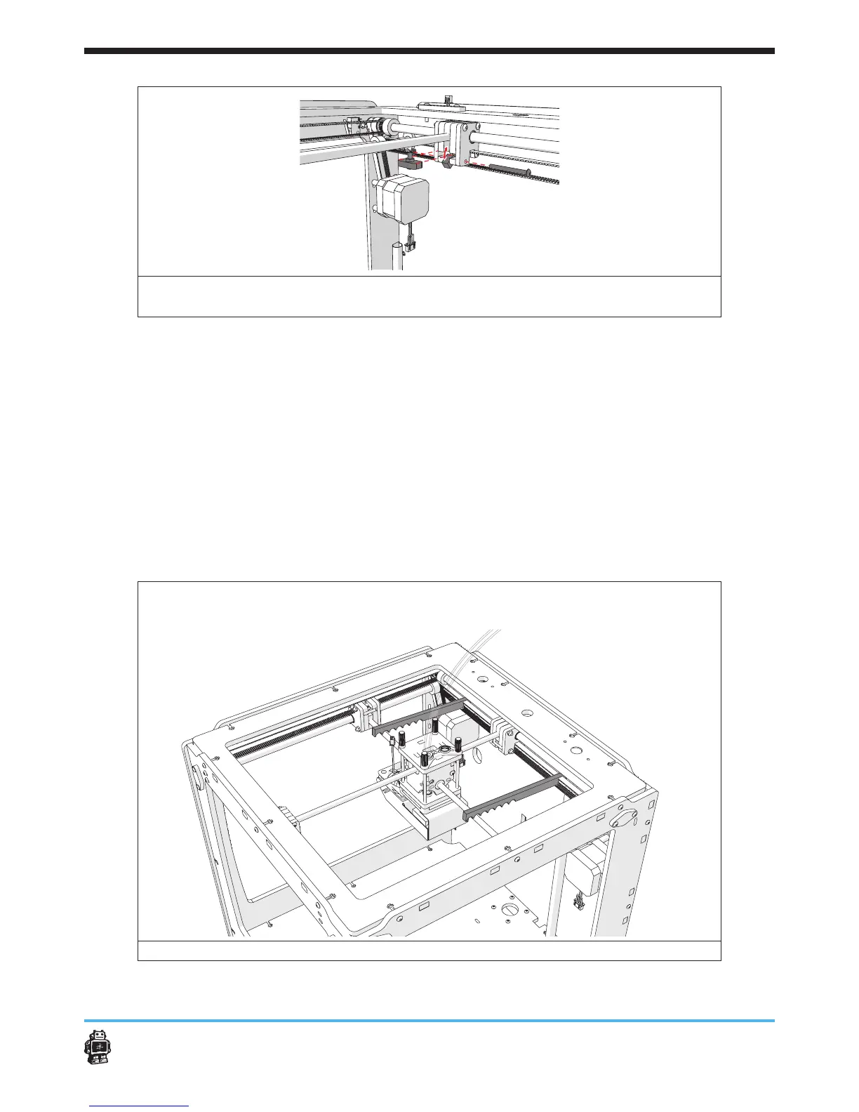
Step 3: attaching the housing on the XY frame Assembling the extrusion head 55
image 67: moving the wooden part C into the FRONT, BACK and RIGHT slider block
and attach with ONE bolt M3 x 30mm
To calibrate the XY-gantry perform the following steps:
11. Align the X axis of the extruder head.
Use two spacers.
12. Tighten the timing pulleys which are attached to the LEFT timing belt,
see image 68 and 69.
5 NOTICE: make sure the spacers use the same notch. Move the RIGHT
sliderblock in the correct position if needed.
13. Tighten the timing pulleys which are attached to the RIGHT timing belt.
5 NOTICE: use another notch if the timing pulleys can not be reached.
14. Repeat step 13 and 14 for the Y axis, FRONT timing pulley and BACK
timing pulley.
image 68: tighting the timing pulleys by using spacers





 To Next Page