TL33 Work Platform 3-3
3.2 Controls and Indicators
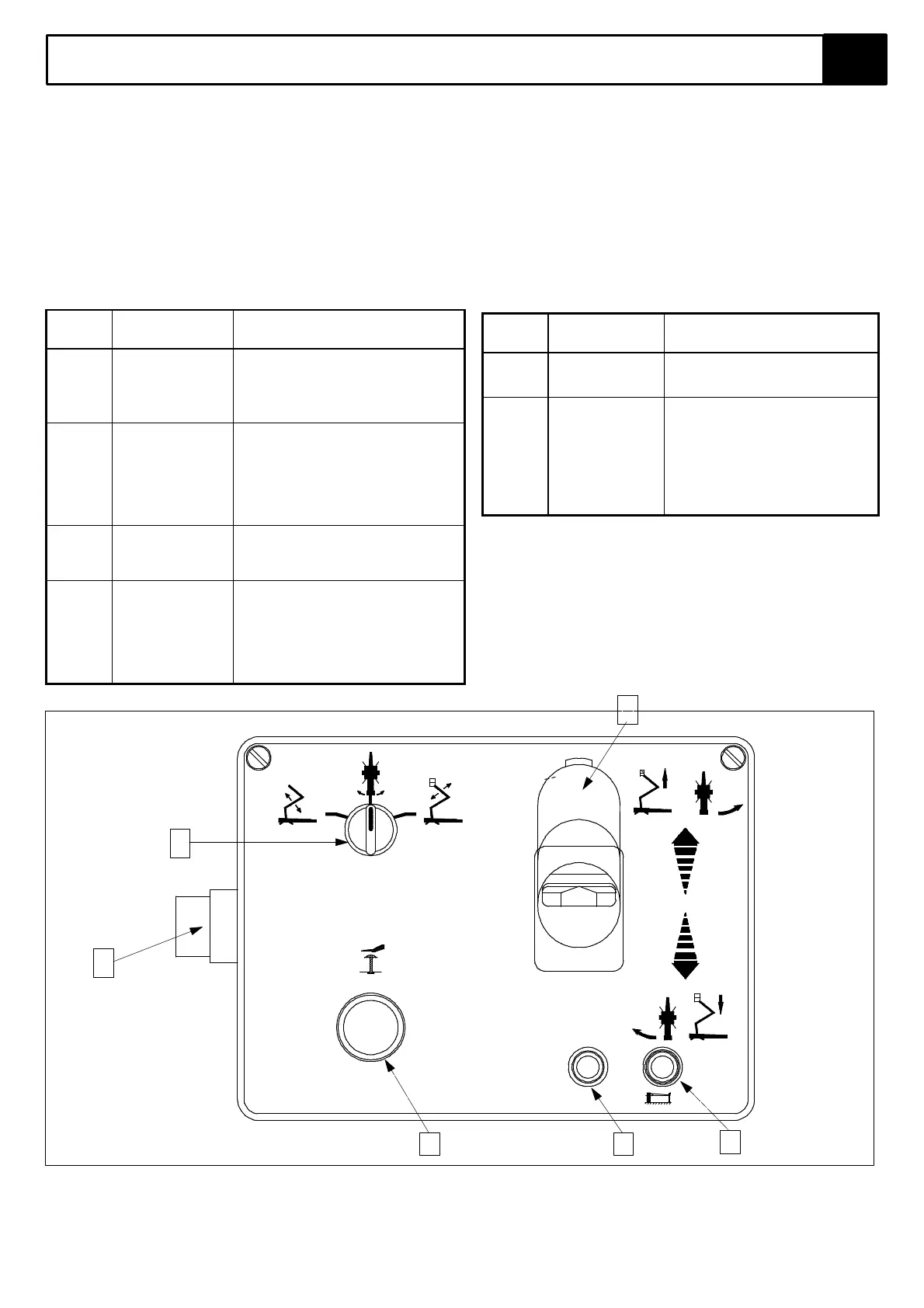
The controls and indicators for operation of the TL33 Work Platform are shown in Figures 3-1 & 3-2. The name and
function of each control and indicator are listed in Tables 3-1 & 3-2. The index numbers in the figure correspond to the
index numbers in the table. The operator should know the location of each control and indicator and have a
thorough knowledge of the function and operation of each before attempting to operate the unit.
The controls and indicators for operation of the TL33 Work Platform are shown in Figure 3-1. The name and function of
each control and indicator are listed in Table 3-1. The index numbers in Figure 3-1 correspond to the index numbers in
Table 3-1. The operator should know the location of each control and indicator and have a thorough knowledge of the
function and operation of each of these before attempting to operate the unit.
Table 3-1: Platform Controls and indicators
INDEX
NO.
NAME FUNCTION
1 SWITCH :-
ON / OFF -
EMERGENCY
OVERRIDE
Turn clockwise for power 'ON', in centre
position for power 'OFF' and
anticlockwise for 'EMERGENCY
OVERRIDE'. (Must be held against
spring pressure in this position)
2 FUNCTION
SELECTOR
Select function to be operated.
SELECTOR: Left hand position for
BOOM 1, centre for ROTATE and right
for BOOM 2 operation.
Left hand position for BOOM 1 , centre
for ROTATE and right for BOOM 2
operation.
3 EMERGENCY
STOP
SWITCH
Push red button to cut off power to all
functions(OFF). Turn clockwise to
release and restore power (ON).
4 JOYSTICK
CONTROL
LEVER
Squeeze to activate Deadman control
and push forward to activate lift or rotate
left function (dependent upon position of
Function Selector2).
Pull back for boom lower or rotate right.
The speed each function operates is
dependent on how far the ever is moved.
INDEX
NO.
NAME FUNCTION
5 SYSTEM OK
INDICATOR
Illuminates to indicate outrigger
interlocks are activated. If not
illuminated check outrigger set-up
immediately (alarm will sound also.
6 BATTERY
CONDITION
INDICATOR
This red L.E.D. indicates the
condition of the batteries. It is
constantly illuminated when the
batteries are fully discharged. It
flashes repeatedly when the batteries
have begun to discharge.
It remains off when the batteries are
fully charged.
Figure 3-1: Platform Controls
1
2
3 6
5
O.K.
4
UpRight
TL33
EMERGENCY STOP