4-11
Section
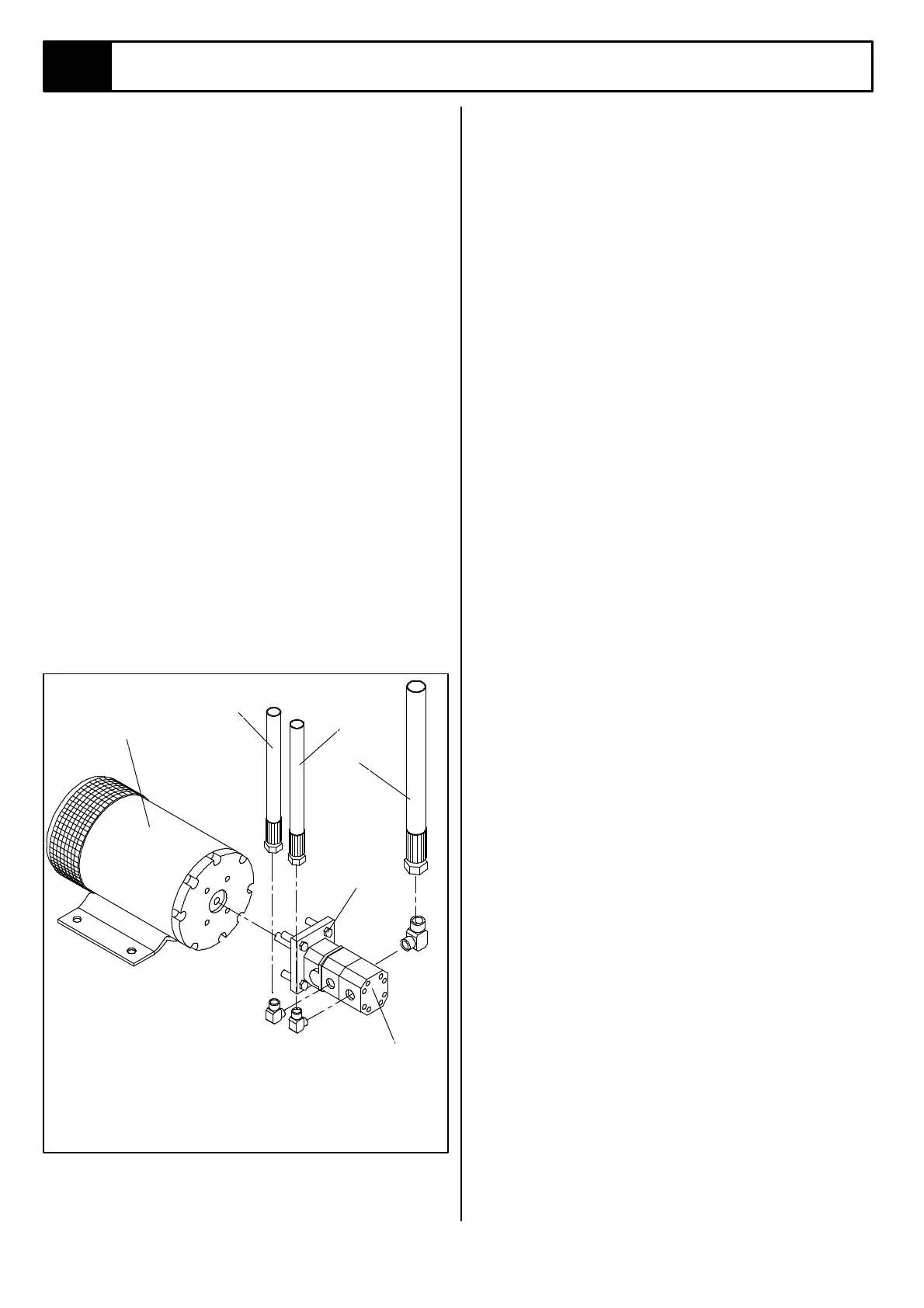
4.8 Hydraulic Pump
(Figure 4-8)
REMOVAL
NOTE: If the hydraulic reservoir has not been drained,
suitable means for plugging the hoses should be
provided to prevent excessive fluid loss.
1. Mark, disconnect and plug hose assemblies.
2. Loosen the capscrews and remove the pump
assembly from the motor.
INSTALLATION
1. Lubricate the pump shaft with general purpose
grease and attach the pump to the motor with the
capscrews.
2. Using a criss-cross pattern torque each capscrew a
little at a time until all the capscrews are torqued to
20 ft.lbs. (27 N-m).
3. Unplug and reconnect the hydraulic hoses.
4. Check the oil level in the hydraulic tank before
operating the work platform.
Figure 4-8: Hydraulic Pump
4.9 Wheel Hubs/Bearings
MAINTENANCE & ADJUSTMENT
1. On level ground, jack up the TL33 with the outriggers
so that the wheels are clear of the ground.
2. Slacken the brakes by turning the hexagon adjusting
nut (Figure 4-11 item 1) anticlockwise.
3. If movement can be detected between the brake drum
and brake backplate, adjust as follows:
a) With a screwdriver blade inserted between the
flange of the grease cap and the hub, remove the
cap. (See Figure 4-9.1).
b) Straighten and remove the split pin from the axle
nut. (See Figure 4-9.2).
c) Tighten the axle nut clockwise until resistance is felt
when rotating the hub by hand.
d) Slacken the nut one slot (30º) anticlockwise, and
refit new split pin. Replace new grease cap.
e) Adjust brakes. (See section 4-10)
REPLACING WORN BEARINGS/ HUB OIL SEAL
1. Remove hubs following procedure from 1 to 3.b above.
2. Remove oil seal and bearing cone (with rollers),
remove
bearing cup by using a 'drift' or bar through the hub
bore, and tapping the cup and oil seal out with a
hammer. (See Figure 4-9.3 )
3. Clean hub thoroughly with a cleaning fluid.
4. Using a suitable soft plug/jig, tap bearing into hub
recess. Ensure that the tapered side of the bearing is
facing outwards (See Figure 4-9.4) and bearing is fully
located against shoulder in hub.
5. Pack bearings with good quality high melting point
grease. Half fill hub cavity with grease.
6. Locate back bearing in hub with rollers facing inwards,
tap oil seal into position.
7. Assemble hub and adjust as described in paragraphs
3c - 3e above.
5
4
1
3
2
6
1. Inlet Hose
2. Outlet Hose
3. Outlet Hose
4. Capscrew
5. Pump Assembly
6. Electric Motor