4-13
Section
4.10 Braking System
PRINCIPLES OF OPERATION
The Auto Reversing arrangement is fitted to each wheel
brake. One 'Shoe' in each brake is fitted with a device that
allows the shoe to slide down on cams or rollers when the
brake drum is rotated in reverse, thus reducing the overall
brake diameter and resistance to movement. In forward
motion, the brake shoe is drawn back to its normal
operating position for forward braking.
To overcome the tendency for the auto-reverse function to
disengage the brakes when parked facing up-hill, an
'energy-store' in the form of a spring in the handbrake lever
mechanism is fitted. This maintains sufficient pressure on
the brakes in the reverse mode, preventing the TL33 from
moving backwards.
NOTE: The handbrake must be applied sufficiently to
ensure that the spring energy store is fully
compressed. Prior to the brakes being 'bedded in' (850
Km or 500 miles from new or from brake shoe change)
care must be taken during normal braking, and when
using the handbrake for parking it is advisable to
chock the wheels for safety.
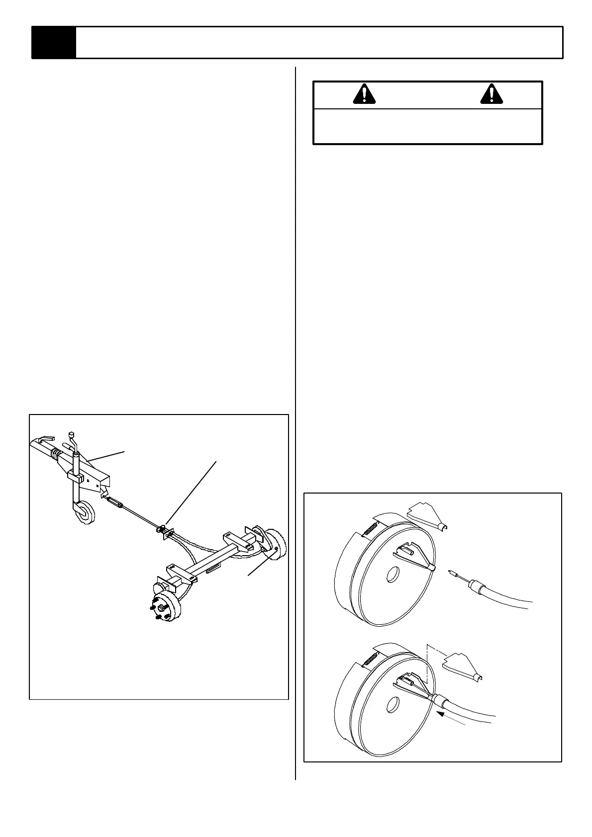
Figure 4-11: Braking Arrangement
ADJUSTMENT OF WHEEL BRAKES
Take care not to inhale brake dust when working
on brakes. Wear a filter mask.
Position the machine on level ground. Ensure handbrake is in the
fully OFF position.
1. Jack wheels clear of the ground.
2. Ensure that handbrake cables are slacked.
3.. Rotate wheels in the forward direction (clockwise on the
right hand side of trailer, anti clockwise on the left hand
side) and tighten adjustment nut (Fig. 4-11 item 1) in a
clockwise direction until hubs will no longer rotate.
4. Slacken the adjustment nut until very slight resistance
is felt between the brakes and brake drum.
5. When adjusting the brakes, ensure that the shoes only
just touch the inside of the brake drums. In order for the
system to work correctly in the reverse mode, the brake
drums must rotate in reverse sufficiently to disconnect
and collapse the auto reverse shoe. The moving tube
inside the coupling must continue to stroke fully and
rest on a "stop" without re-applying the brakes. If the
brakes are adjusted too tightly to the drums then the
coupling will again apply the brakes and prevent further
reverse movement.
6. Re-adjust cables & test function.
CHANGING WORN OR DAMAGED BRAKE
CABLES
1. Check brake cable where it enters brake. If it ends in a
collar that fits over the cable entry tube then the cables
are of the detachable type.
2. To change the cable, slacken and drop cable end from
the Equalizer plate (Fig. 4-11 item 3) and detach cables
from drum as shown in Figure 4-12 (a) .
3. To refit, reverse the procedure.
Figure 4-12: Replace Brake Cable
3
1
2
1. Brake Shoe Adjustment
2. Handbrake
3. Equalizer plate
WARNING
(b)
(a)
Remove top half of
cable bracket and
remove cable.
Replace top half of
cable bracket and
over bracket
assembly.