TL33 Work Platform 4-8
OUTRIGGER LIMIT SWITCHES
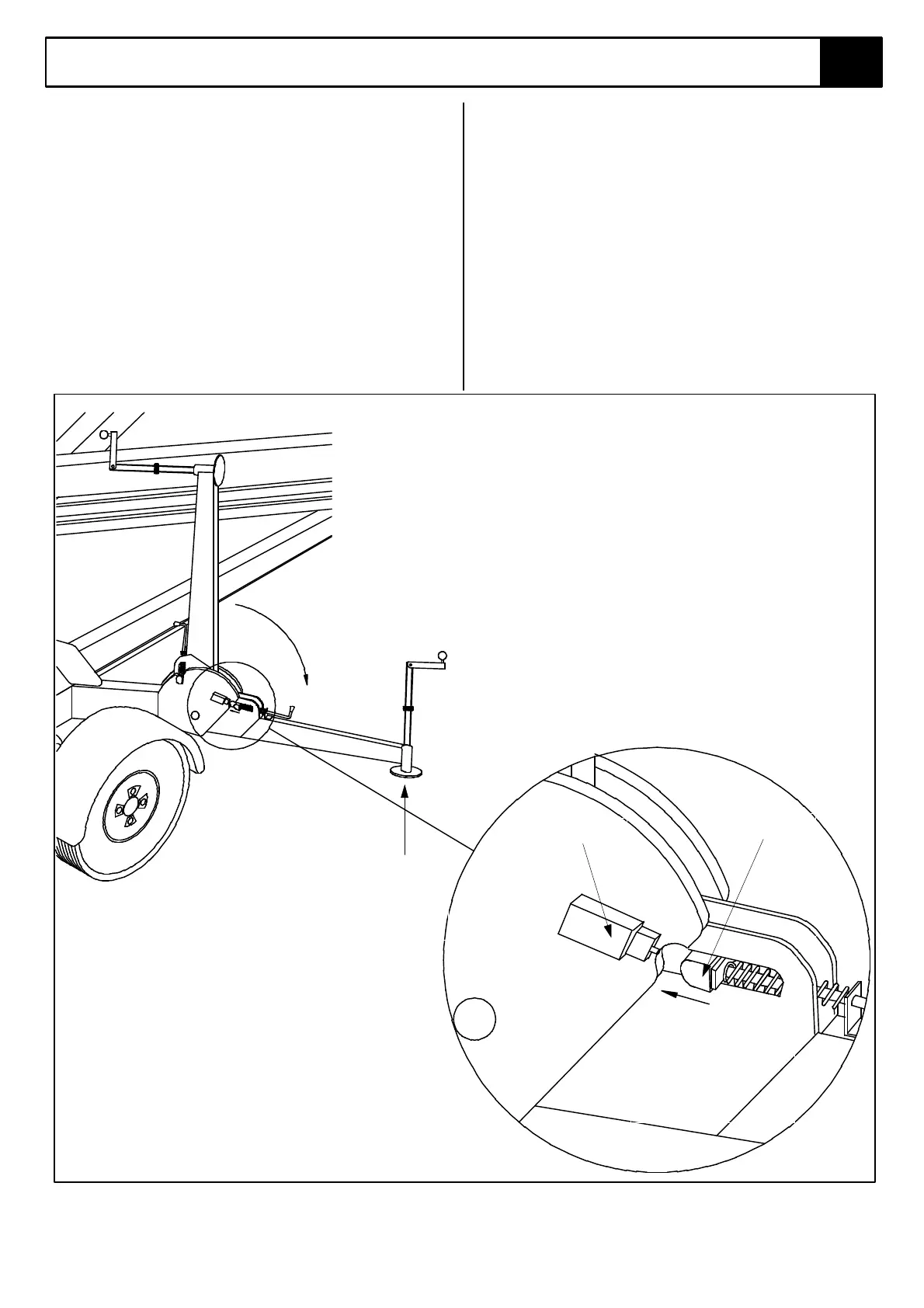
Function: These four limit switches are wired in series.
When the four outriggers are deployed these switches
are activated and allow the booms functions to be
operated.
In addition, the switches also provide warning if one of
the outriggers becomes ‘light’ or lifts off the ground. In
this case power is cut to the upper controls and the
alarm is acitvated.
Location: On the outrigger pivot plates.
Adjustment:
The limit switch head is non-adjustable and should be
depressed by the outrigger locking pin the outriggers are
deployed and taking load. It should be checked for
freedom of movement and kept clean from dirt or other
contaminants. Ensure all moving parts on locking
mechanism (springs, etc.) are in good working order and
lubricated regularly.
Figure 4-6: Outrigger Limit Switches
Limit switch
Locking pin
Vertical load increases
as jack is screwed
down forcing locking
pin further into the slot.
Outrigger locking pin
moves in further and
strikes limit switch
plunger when load is
applied to outrigger
jack.