TL33 Work Platform 6-3b
Sectio
n
6.1 Electrical Schematic SERIAL NUMBERS: 1133 TO 1330
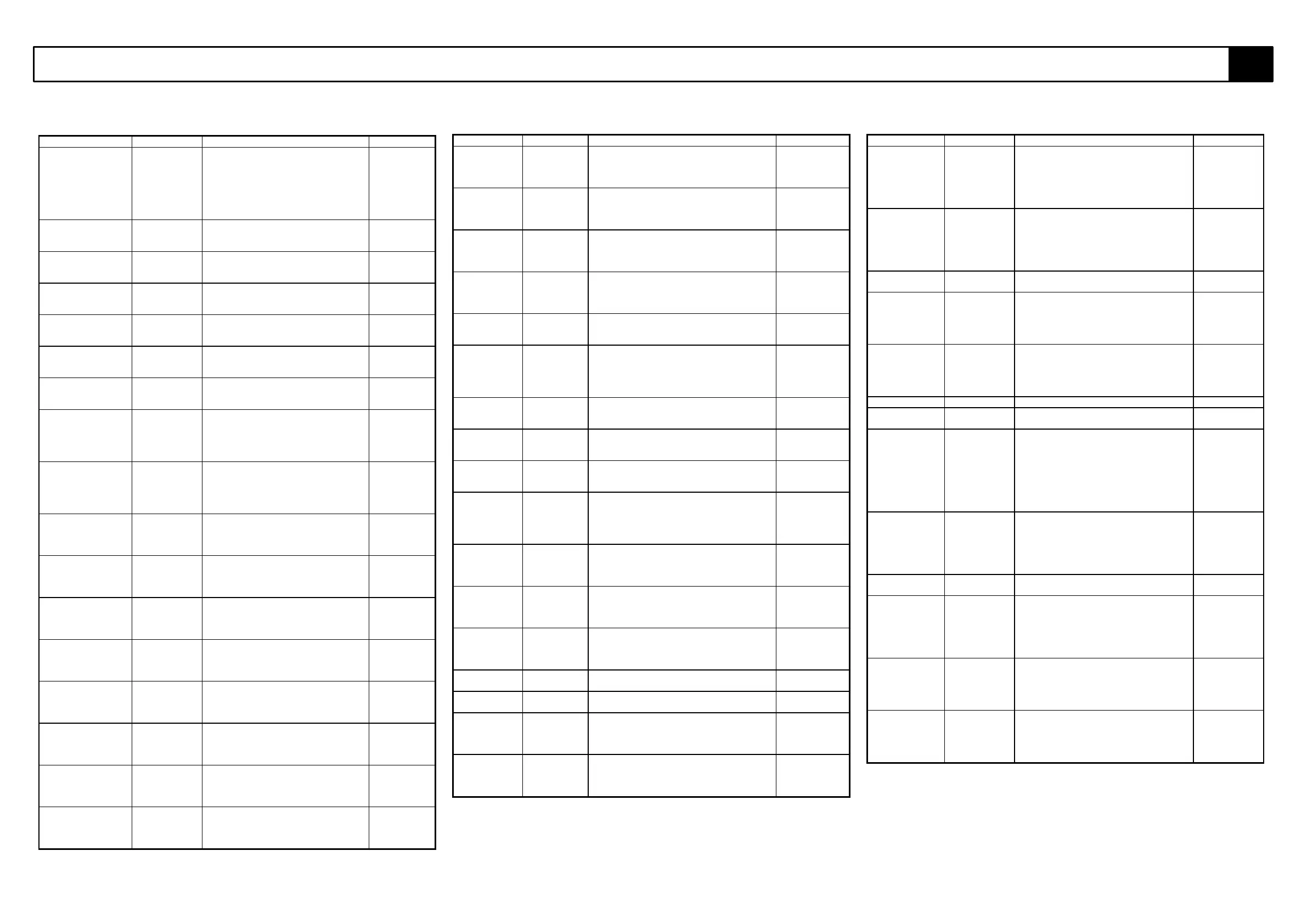
Table 6-1: Electrical Schematic Legend
REFERENCE NAME FUNCTION LOCATION
ALM1 Alarm,Tilt. Provides warning sound until
outriggers are deployed and the
contacts on LS1, LS2, LS3 and LS4
are closed. If one of the switches
opens during the operation of the
machine then the alarm sounds and
power is cut to the upper controls.
Upper
Control Box.
BAT Batteries x
(4). 6 Volts
each.
Power supply. Chasis
subframe
BC1 24V Battery
Charger.
This chargers the 4 x 6v batteries
when switched on and the line
contactor is unergised.
Chasis
Subframe.
D1 Diode Feeds +24V to pin 6 on the controller
from upper controls.
Lower
control box
PCB.
D2 Diode Feeds +24V to pin 6 on the controller
when the keyswitch is switched to
lower controls.
Lower
control box
PCB.
D3 TO D8 Diode Suppression diodes for coils of
hydraulic solenoids.
Lower
control box
PCB.
D9 Diode prevents feedback to alarm ALM1
whens relays k1 and k2 are energised
Lower
control box
PCB.
D10 Diode Feeds a signal from lower lift cylinder
(down) solenoid to pin 4 on the
controller and prevents feedback to
the lift solenoid when other functions
are selected.
Lower
control box
PCB.
D11 Diode Feeds a signal from upper lift
cylinder (down) solenoid to pin 4 on
the controller and prevents feedback
to the lift solenoid when other
functions are selected.
Lower
control box
PCB.
D12 Diode Feeds power to slew left solenoid
from upper controls and prevents
feedback to upper controls from the
lower controls
Lower
control box
PCB.
D13 Diode Feeds power to slew left solenoid
from lower controls and prevents
feedback to lower controls from the
upper controls
Lower
control box
PCB.
D14 Diode Feeds power to the lower cylinder
(up) solenoid from upper controls
and prevents feedback to upper
controls from lower controls.
Lower
control box
PCB.
D15 Diode Feeds power to the lower cylinder
(up) solenoid from lower controls and
prevents feedback to lower controls
from upper controls.
Lower
control box
PCB.
D16 Diode Feeds power to the upper cylinder
(up) solenoid from upper controls
and prevents feedback to upper
controls from lower controls.
Lower
control box
PCB.
D17 Diode Feeds power to the upper cylinder
(up) solenoid from lower controls and
prevents feedback to lower controls
from upper controls.
Lower
control box
PCB.
D18 Diode Feeds power to slew right solenoid
from upper controls and prevents
feedback to upper controls from the
lower controls
Lower
control box
PCB.
D19 Diode Feeds power to slew right solenoid
from lower controls and prevents
feedback to lower controls from the
upper controls
Lower
control box
PCB.
REFERENCE NAME FUNCTION LOCATION
D20 Diode Feeds power to the lower cylinder (down)
solenoid from upper controls and prevents
feedback to upper controls from lower
controls.
Lower control
box PCB.
D21 Diode Feeds power to the lower cylinder (down)
solenoid from lower controls and prevents
feedback to lower controls from upper
controls.
Lower control
box PCB.
D22 Diode Feeds power to the upper cylinder (down)
solenoid from upper controls and prevents
feedback to upper controls from lower
controls.
Lower control
box PCB.
D23 Diode Feeds power to the upper cylinder (down)
solenoid from lower controls and prevents
feedback to lower controls from upper
controls.
Lower control
box PCB.
D24 Diode Feeds power signal from joystick trigger to
pin 4 on controller when emergency
override is activated
Lower control
box PCB.
D25,D26 Diode Feed the signal which comes from the
keyswitch (set at upper controls) to one of
the alarm relay contacts and prevent
power getting to upper controls when the
alarm is activated from the lower controls.
Lower control
box PCB.
D27 Diode Prevents backfeed to pin 4 on the
controller when the a signal is sent to the
line contactor from the jostick trigger.
Lower control
box PCB.
D28 Diode Prevents backfeed to lower control contact
of the keyswitch when the line contactor is
energised.
Lower control
box PCB.
D29 Diode It prevents backfeed to the lower control
switches when the alarm is activated from
upper controls.
Lower control
box PCB.
D30 Diode Feeds a signal to the line contactor when
the joystick trigger is depressed. It
prevents backfeed to the upper controls
when the line contactor is energised by
the lower controls.
Lower control
box PCB.
D31 Diode Allows the feed to the alarm for
continuous operation in tilt. Prevents the
continuous alarm during intermittent
outrigger operation
Lower control
box PCB.
D32 Diode Feeds the tilt alarm switch when the key
switch is set to lower controls and
prevents feedback when the keyswitch is
set to upper controls.
Lower control
box PCB.
D33 Diode Feeds the tilt alarm switch when the key
switch is set to upper controls and
prevents feedback when the keyswitch is
set to lower controls.
Lower control
box PCB.
D34 Diode Suppression diode for the coil of direction
relay 1 (RL1)
Upper Control
Box P.C.B.
D35 Diode Suppression diode for the coil of direction
relay 2 (RL2)
Upper Control
Box P.C.B.
D36 Diode Feeds power to joystick at upper controls .
It also prevents a feedback to normal
upper controls when the emergency
override is being operated.
Upper Control
Box.
D37 Diode Feeds a signal from lower lift cylinder (up )
solenoid to pin 4 on the controller and
prevents feedback to the lift solenoid
when other functions are selected.
Lower control
box PCB.
REFERENCE NAME FUNCTION LOCATION
D79 & D81 Diode. Feeds a signal to pin 8 on the controller
when the lower cylinder lift function is
selected at the upper controls. It
prevents backfeed to the lower lift
solenoid when the upper lift cylinder
solenoid is energised.
Upper Control
Box P.C.B.
D80 & D82 Diode. Feeds a signal to pin 8 on the controller
when the upper cylinder lift function is
selected at the upper controls. It
prevents backfeed to the upper lift
solenoid when the lower lift cylinder
solenoid is energised.
Upper Control
Box P.C.B.
D83 Diode Suppression diode for coil of line
contactor.
LC1
D84, D85 Diode Feed a signal to pin 4 on the controller
when slew is energised from the lower
controls. They prevent backfeed to the
slew solenoids when a signal is fed
through D24 to pin 4 on the controller
Lower control
box PCB.
D9 Diode Feeds a signal from upper lift cylinder
(up ) solenoid to pin 4 on the controller
and prevents feedback to the lift
solenoid when other functions are
selected.
Lower control
box PCB.
FU1 Fuse 7Amps Overload protection for curcuit. On MCU
FU2 Fuse
160Amps
Overload protection for Electric motor. On MCU
K1 Alarm Relay. This relay is energised when the four
outrigger limit switches are activated the
normally closed contacts which feed
power to the alarm are opened and the
alarm switches off. If an outrigger limit
switch opens during operation of the
booms the relay de-energises and the
alarm sounds.
On lower
control box
PCB.
K2 Relay. This Relay is constantly energised
through the tilt alarm. The normally
open contacts remain closed in this
state and feed the upper controls with
power when the keyswitch is turned to
the upper controls.
On lower
control box
PCB.
KSW1 Keyswitch 3-
position
Diverts power to either upper or lower
control boxes.
Lower control
box.
LC1 Line
Contactor.
In the unergised state the normally
closed contacts allow the charger +ve to
the batteries. In the
energised stete the normally open
contacts contacts close and route the
battery +ve to the pump motor.
On the motor
control unit
on the chasis
subframe.
LED 1 Battery
Indicator.
(Red)
The LED remains off when the batteries
are fully charged. The LED flashes when
the batteries begin to discharge. The
LED will remain on when the batteries
are fully discharged.
Upper Control
Box.
LED2 Outrigger
LED (Green)
This LED is illuminated when the
outriggers are deployed and taking load.
If an outrigger becomes “light” and
comes off the ground this LED will go
off and the alarm will sound.
Upper Control
Box.