72 • vacon parameter descriptions
Tel. +358 (0)201 2121 • Fax +358 (0)201 212205
9
FWD
REV
Set
frequency
Set
frequency
0 Hz
Run enable
Ctrl signal 1
Ctrl signal 2
Keypad
start button
Keypad
stop button
1 2 3 4 5 6 7 8 9
10 11 12
Output
frequency
t
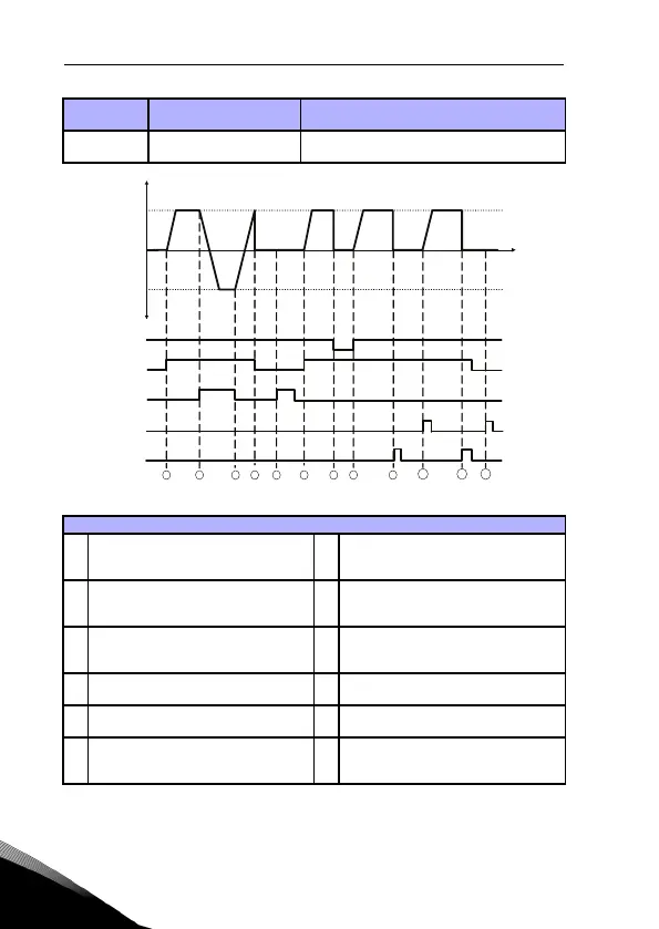
Figure 9.6: Start/Stop logic, selection 3
Selection
number
Selection name Note
3
CS1:Start
CS2:Reverse
Explanations:
1 Control signal (CS) 1 actives causing the
output frequency to rise. The motor runs
forward.
7 Run enable signal is set to FALSE, which
drops the frequency to 0.The run enable
signal is configured with par. 5.7.
2 CS2 activates which causes the direction
to start changing (FWD to REV).
8 Run enable signal is set to TRUE, which
causes the frequency to rise towards the
set frequency because CS1 is still active.
3 CS2 is inactivated which causes the
direction to start changing (REV to FWD)
because CS1 is still active.
9 Keypad stop button is pressed and the
frequency fed to the motor drops to 0.
4 Also CS1 inactivates and the frequency
drops to 0.
10 The drive starts through pushing the
Start button on the keypad.
5 Despite the activates of CS2,the motor
does not start because CS1 is inactive.
11 The drive is stopped again with the Stop
button on the Keypad.
6 CS1 activates causing the output fre-
quency to rise again. The motor runs
forward because CS2 is inactive.
12 The attempt to start the drive through
pushing the Start button is not success-
ful because CS1 is inactive.