90 • vacon parameter descriptions
Tel. +358 (0)201 2121 • Fax +358 (0)201 212205
9
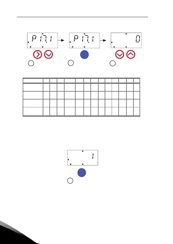
Figure 9.19: Drive setup
1
2
3
4
1,1 x
I
NMOT
1,1 x
I
NM OT
1,5 x
I
NMOT
Selections:
Parameters
affected:
P1.1 Motor Un (V)
P1.2 Motor fn (Hz)
P1.7 Current limit (A)
P1.8 Motor control mode
P1.15 Torque boost
P2.1 Control place
P2.2 Start function
P2.3 Stop function
P3.1 Min frequency
P3.2 Max frequency
P3.3 I/O reference
P4.2 Acc. time (s)
P4.3 Dec time (s)
*Same as drive voltage,
except in 115V drives
this value is 230V
P1.1 P1.2 P1.7 P1.8 P1.15 P2.1 P2.2 P2.3 P3.1 P3.2 P3.3 P4.2 P4.3
Startup wizard
showns par 17.1
number.
Press OK to enter
edit mode.
Press OK to
confirm
drive setup
Select between
0-3, see below!
0 = Basic
1 = Pump drive
2 = Fan drive
3 = High Torque
drive
V*
V*
V*
V*
50/60
Hz
50/60
Hz
50/60
Hz
50/60
Hz
50/60
Hz
50/60
Hz
50/60
Hz
50/60
Hz
0=
Not
used
0=
Frequecny
control
0=
Frequecny
control
0=
Frequecny
control
1=Open
loop speed
ontrol
0=
Not
used
0=
Not
used
1=
used
I/O
I/O
I/O
I/O
0=
Ramp
0=
Ramp
1=
Ramp
1=
Flying
0=
Ramp
0=
Coast
0=
Coast
0=
Coast
0 Hz
0 Hz
20 Hz
20 Hz
4=AI1
0-10V
3s 3s
5s 5s
1s 1s
20s20s
OK
OK
READY RUN STOP ALARM FAULT
REF
MON
PAR
SYS
READY RUN STOP ALARM FAULT
FWD REV I/O KEYPAD
BUS FWD REV I/O KEYPAD
BUS FWD
REV I/O KEYPAD BUS
READY RUN STOP ALARM FAULT
REF
MON
PAR
SYS
REF
MON
PAR
SYS
READY RUN STOP ALARM FAULT
REF
MON
PAR
SYS
FWD REV I/O KEYPAD BUS
1,5 x
I
NMOT
4=AI1
0-10V
4=AI1
0-10V
4=AI1
0-10V