EasyManuals Logo

Vacon 20 SERIES User Manual

Vacon 20 SERIES
72 pages
To Next Page IconTo Next Page
To Previous Page IconTo Previous Page
Page #16 background imageLoading...
Page #16 background image
vacon • 13 Description of Groups
2
2.1.4 Drive
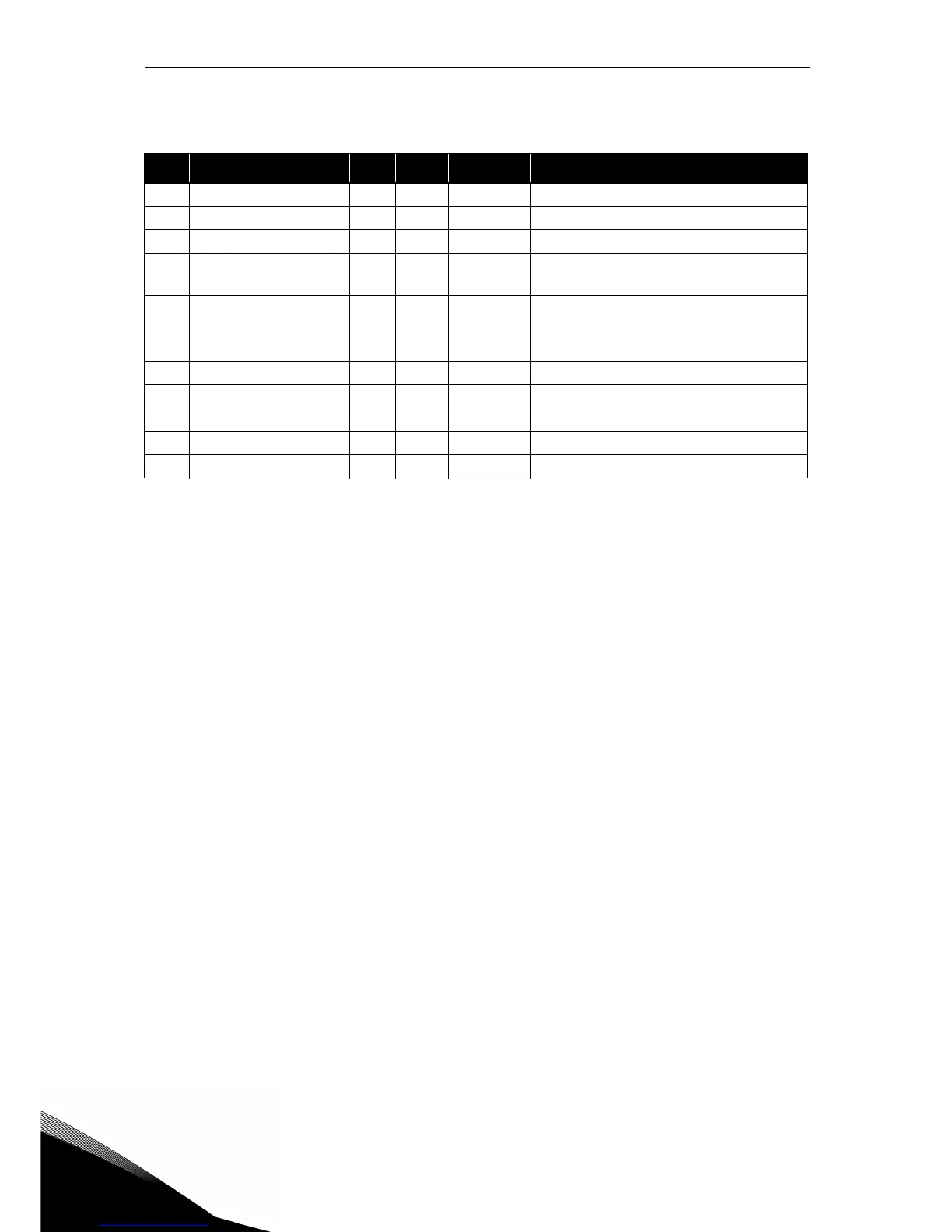
Table 28: Drive monitoring items.
Code Monitoring value Unit ID Level Description
V4.1 DC link voltage V 7 Advanced
V4.2 Unit temperature °C 8 Advanced Heatsink temperature
V4.3 Board temperature °C 1825 Service Power board temperature
V4.4
Actual output
frequency
Hz 10 Service
Output frequency inclusive slip com-
pensation
V4.5
Droop frequency
reference
Hz 25 Service
Frequency setpoint inclusive droop
correction
V4.6 Analogue input 1 % 13 Service Analogue input AI1
V4.7 Analogue input 2 % 14 Service Analogue input AI2
V4.8 DI3, DI2, DI1 15 Service Digital inputs status
V4.9 DI6, DI5, DI4 16 Service Digital inputs status
V4.10 DO, RO2, RO1 17 Service Digital outputs status
V4.11 Analogue output % 26 Service Analogue output

Questions and Answers:

Question and Answer IconNeed help?

Do you have a question about the Vacon 20 SERIES and is the answer not in the manual?

Vacon 20 SERIES Specifications

General IconGeneral
Output Voltage0 to Input Voltage
Storage Temperature-40°C to +70°C
DimensionsVaries by model
WeightVaries by model
Power Range0.25 kW to 18.5 kW
Voltage Range200 V to 480 V
Control MethodSensorless vector control
Protection ClassIP20
Ambient Temperature-10°C to +50°C
Communication OptionsModbus, CANopen
EMC FilterIntegrated
STO (Safe Torque Off)Yes
Input Voltage208-240 V, 380-480 V
Protection FeaturesOvervoltage, Undervoltage, Overcurrent, Overtemperature
Operating Temperature-10°C to +50°C
Humidity5% to 95% non-condensing

Related product manuals