Description of Groups vacon • 28
Service support: find your nearest Vacon service center at www.vacon.com
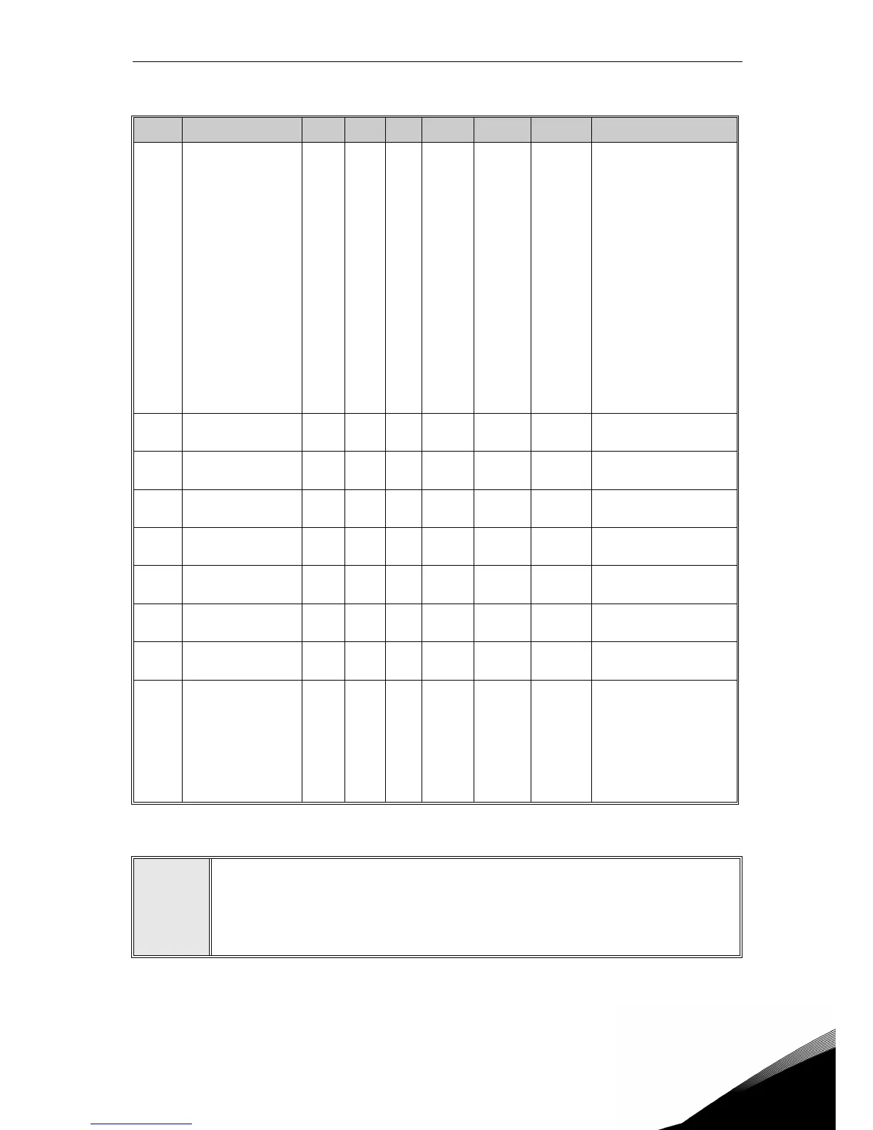
2
2.2.12 Group Non-ASi fieldbus: Menu PAR G12
Code Parameter Min Max Unit Default ID Level Description
P12.1
Fieldbus Data OUT 1
selection
0 10 0 852
Basic /
Service
2)
Variable mapped on PD1:
0 = Output current
1 = Motor speed
2 = Motor current
3 = Motor voltage
4 = Motor torque
5 = Motor power
6 = DC-link voltage
7 = Active fault code
8 = Analogue AI1
9 = Analogue AI2
10 = Digital inputs state
11 = PID feedback value
12 = PID setpoint
13 = Analogue AI3
14 = Temperature 1
15 = Temperature 2
16 = Temperature 3
P12.2
Fieldbus Data OUT 2
selection
0 10 1 853
Basic /
Service
2)
Variable mapped on PD2.
See P12.1
P12.3
Fieldbus Data OUT 3
selection
0 10 2 854
Basic /
Service
2)
Variable mapped on PD3.
See P12.1
P12.4
Fieldbus Data OUT 4
selection
0 10 4 855
Basic /
Service
2)
Variable mapped on PD4.
See P12.1
P12.5
Fieldbus Data OUT 5
selection
0 10 5 856
Basic /
Service
2)
Variable mapped on PD5.
See P12.1
P12.6
Fieldbus Data OUT 6
selection
0 10 3 857
Basic /
Service
2)
Variable mapped on PD6.
See P12.1
P12.7
Fieldbus Data OUT 7
selection
0 10 6 858
Basic /
Service
2)
Variable mapped on PD7.
See P12.1
P12.8
Fieldbus Data OUT 8
selection
0 10 7 859
Basic /
Service
2)
Variable mapped on PD8.
See P12.1
P12.9
ASi Outputs
emulation
2)
0 5 0 1821
Basic /
Service
2)
PDI used as ASi outputs
emulator.
0 = Not used
1 = PDI1
2 = PDI2
3 = PDI3
4 = PDI4
5 = PDI5
Table 41: Group Non-ASi fieldbus.
NOTE!
1)
Parameters of this group are visible at Basic level when ASi board is not
installed. They are anyway visible at Service level.
2
) A different fieldbus can also simulate ASi interface. Outputs and Inputs will be
mapped on Process Data.
 Loading...


