Description of Groups vacon • 24
Service support: find your nearest Vacon service center at www.vacon.com
2
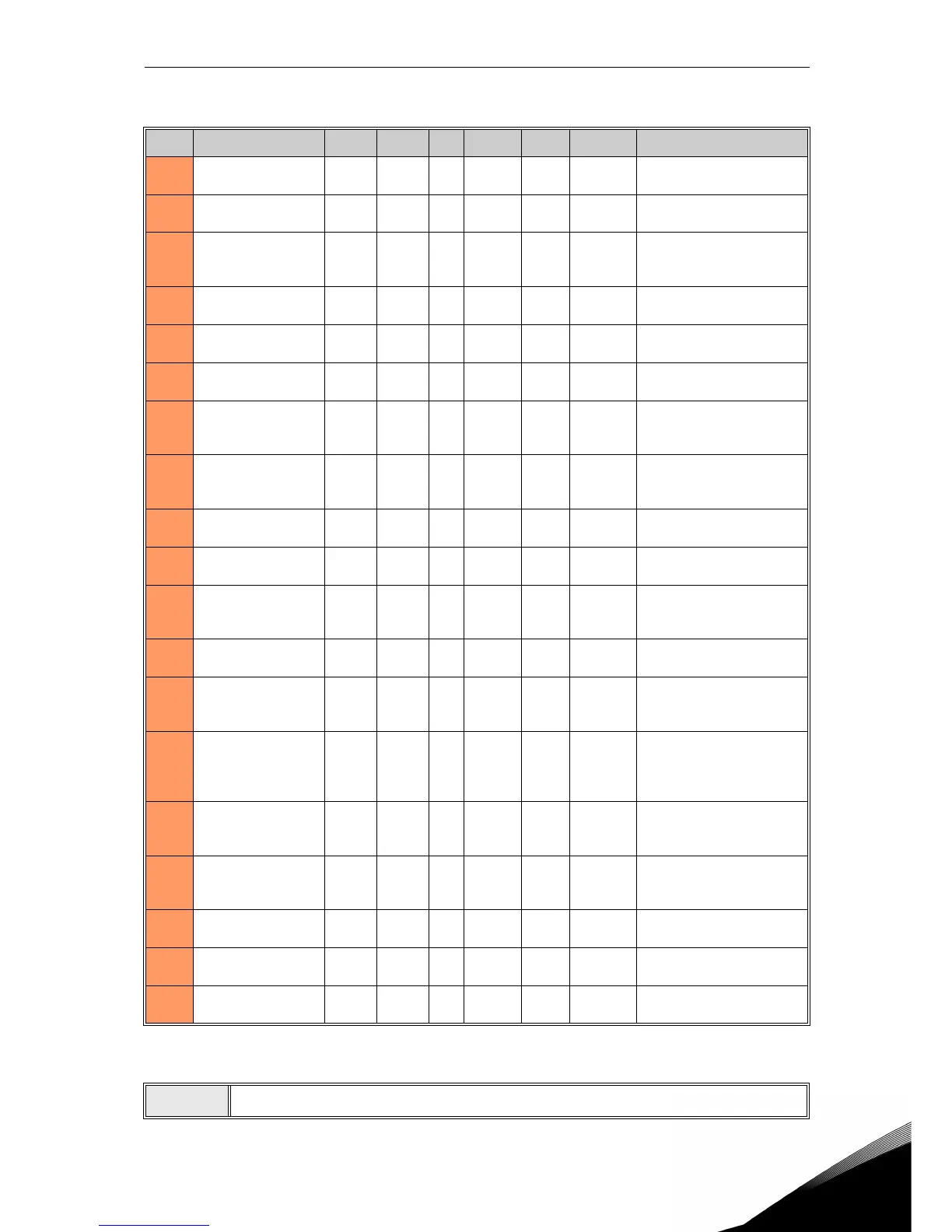
2.2.9 Group Motor Control: Menu PAR G9
Code Parameter Min Max Unit Default ID Level Description
P9.1
Field Weakening
Point frequency
8.00 320.00 Hz 50.00 602 Advanced
Field weakening point fre-
quency
P9.2
Field Weakening
Point voltage
10.00 200.00 % 100.00 603 Advanced
Voltage at FWP as % of
Motor nominal voltage
P9.3 U/f ratio selection(*) 0 2 0 108 Advanced
0 = linear
1 = quadratic
2 = programmable
P9.4
U/f midpoint
frequency(*)
0.00 P9.2 Hz 50.00 604 Advanced
Midpoint frequency for pro-
grammable U/f curve
P9.5
U/f midpoint volt-
age(*)
0.00 P9.3 % 100.00 605 Advanced
Midpoint voltage for pro-
grammable U/f curve
P9.6
Zero frequency
voltage(*)
0.00 40.00 % 0.00 606 Advanced
Voltage at 0,00 Hz as % of
Motor nominal voltage
P9.7 RS voltage drop(*) 0.00 100.00 % 0.00 662 Advanced
Voltage drop on the motor
windings as % of Motor
nominal voltage
P9.8 Switching frequency 1.5 16.0 kHz 4.0 601 Advanced
Increasing the switching
frequency reduces the
capacity of the drive.
P9.9 Drooping Mode 0 1 1 1813 Advanced
0: constant
1: speed dependent
P9.10 Droop filter time 0.00 3.00 s 0.10 1814 Advanced
Constant time of filter on
droop calculation
P9.11 Brake chopper 0 2 0 504 Advanced
0 = Disabled
1 = Enabled in RUN
2 = Enabled in READY
P9.12 Brake chopper level 600 900 V 650 1807 Advanced
DC-link voltage to start
chopper.
P9.13 DC brake current
0.3 x I
H
2 x I
H
A
I
H
507 Basic
Defines the current injected
into the motor during DC-
braking. 0 = Disabled
P9.14
DC braking time at
stop
0.00 600.00 s 0.00 508 Basic
Determines if braking is ON
or OFF and the braking time
of the DC-brake when the
motor is stopping.
P9.15
Frequency to stop DC
braking at ramp stop
0.10 10.00 Hz 1.50 515 Basic
The output frequency at
which the DC-braking is
applied.
P9.16
DC braking time at
start
0.00 600.00 s 0.00 516 Basic
Determines the braking
time of the DC-brake when
the motor is starting.
P9.17
Overvoltage
controller
0 1 0 1853 Service
0 = Enabled
1 = Disabled
P9.18
Undervoltage
controller
0 1 0 1854 Service
0 = Enabled
1 = Disabled
P9.19
Switching frequency
controller
0 1 0 1855 Service
0 = Enabled
1 = Disabled
Table 38: Group Motor control.
NOTE!
(*) Parameter is automatically set by motor identification.
 Loading...


