Description of Groups vacon • 14
Service support: find your nearest Vacon service center at www.vacon.com
2
2.2 Parameter Groups: Menu PAR
The Decentralized Application embodies the following parameter groups:
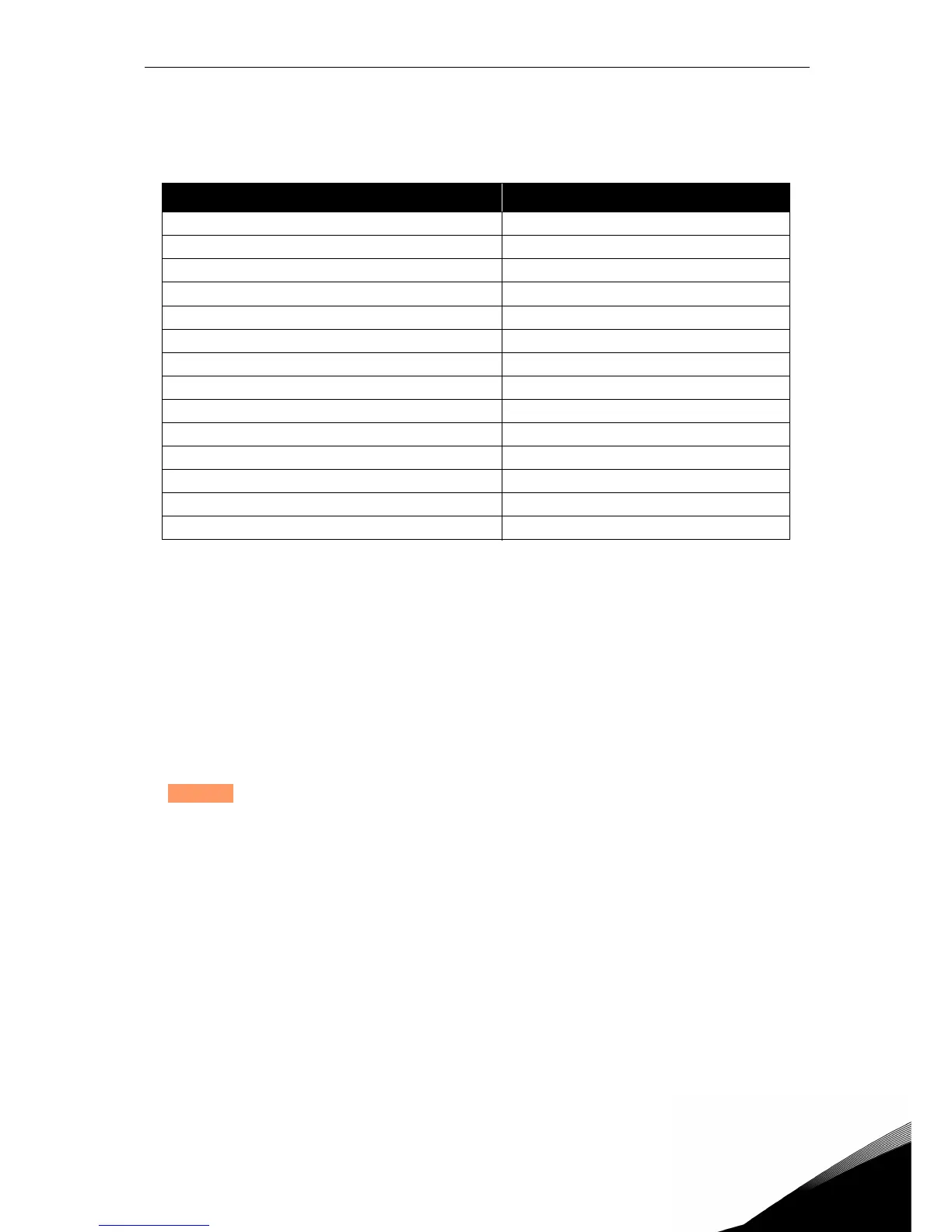
Table 29: Parameter groups
Column explanations:
Code = Location indication on the keypad; Shows the operator the parameter num-
ber.
Parameter= Name of parameter
Min = Minimum value of parameter
Max = Maximum value of parameter
Unit = Unit of parameter value; Given if available
Default = Value preset by factory
ID = ID number of the parameter
Description= Short description of parameter values or its function
= The parameter may be changed only in Stop state
Menu and Parameter group Description
Group Motor settings: Menu PAR G1 Motor settings
Group Start/Stop Settings: Menu PAR G2 Start/Stop and mode settings
Group References: Menu PAR G3 Frequency reference selection
Group Ramps: Menu PAR G4 Ramp times
Group Input functions: Menu PAR G5 Digital input programming
Group Output functions: Menu PAR G6 ASi and digital output programming
Group Mechanical brake: Menu PAR G7 Mechanical brake programming
Group Supervisions: Menu PAR G8 Supervision programming
Group Motor Control: Menu PAR G9 Motor control and U/f parameters
Group Protections: Menu PAR G10 Protections configuration
Group Automatic reset: Menu PAR G11 Auto reset after fault configuration
Group Non-ASi fieldbus: Menu PAR G12 Non-ASi Fieldbus data out parameters
Group Analogue output: Menu Par G13 Analogue output programming
Group User interface: Menu Par G14 User interface parameters
 Loading...


