Description of Groups vacon • 26
Service support: find your nearest Vacon service center at www.vacon.com
2
The torque values for setting the underload curve are set in percentage which refers to the
nominal torque of the motor. The motor's name plate data, parameter motor nominal current
and the drive's nominal current I
L
are used to find the scaling ratio for the internal torque val-
ue. If other than nominal motor is used with the drive, the accuracy of the torque calculation
decreases.
If you use long motor cables (max. 100m) together with small drives (1.5 kW) the
motor current measured by the drive can be much higher than the actual motor
current due to capacitive currents in the motor cable. Consider this when setting up
the motor thermal protection functions.
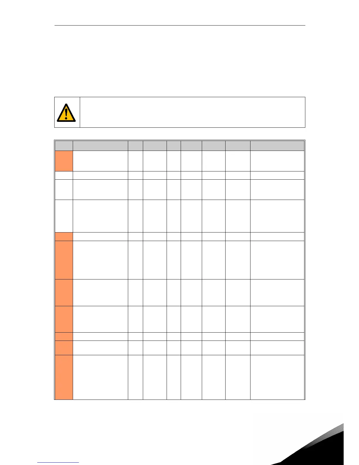
Code Parameter Min Max Unit Default ID Level Description
P10.1 Earth fault 0 2 2 703 Advanced
0 = No action
1 = Warning
2 = Fault
P10.2 Motor stall fault 0 2 1 709 Advanced See P10.1
P10.3 Stall time limit 0.0 300.0 s 5.0 711 Advanced
This is the maximum
time allowed for a stall
stage.
P10.4 Stall frequency limit 0.10 320.00 Hz 15.00 712 Advanced
For a stall state to
occur, the output fre-
quency must have
remained below this
limit for a certain time.
P10.5 Underload fault 0 2 0 713 Advanced See P10.1
P10.6
Underload protection:
Field weakening area
load
10.0 150.0 % 50.0 714 Advanced
This parameter gives
the value for the mini-
mum torque allowed
when the output fre-
quency is above the
field weakening point.
P10.7
Underload fault:
Zero frequency load
5.0 150.0 % 10.0 715 Advanced
This parameter gives
value for the minimum
torque allowed with
zero frequency.
P10.8
Underload fault:
Time limit
1.0 300.0 s 20.0 716 Advanced
This is the maximum
time allowed for an
underload state to
exist.
P10.9 Motor thermal fault 0 2 2 704 Advanced See P10.1
P10.10
Motor ambient
temperature factor
-20 100 °C 40 705 Advanced
Ambient temperature
in °C
P10.11
Motor thermal zero
speed cooling
0.0 150.0 % 40.0 706 Advanced
Defines the cooling
factor at zero speed in
relation to the point
where the motor is
running at nominal
speed without external
cooling.
Table 39: Group Protections.

 Loading...


