User's Guide _______________________________________________________________________
26 ___________________________________________________________________ M211060EN-H
Wiring
For a secure connection to the probe, connect to the 4-pin M8 connector
using a threaded connector.
The grounding method depends on the probe and the installation type.
See Table 5 below.
Table 5 Grounding Methods
It is recommended to use a shielded cable and
connect the shield to ground.
In the shielded cables supplied by Vaisala, the
threaded connector connects the shield to the
HMP110T, HMP110REF
There are two ways to ground the probe depending
on installation type. Choose only one of these
ways:
- Grounding is provided by the metal cover of
the probe. If using shielded cables, shield is
NOT connected to ground.
- A shielded cable is used, and the shield is
connected to ground. In the shielded cables
supplied by Vaisala, the threaded connector
connects the shield to the probe housing.
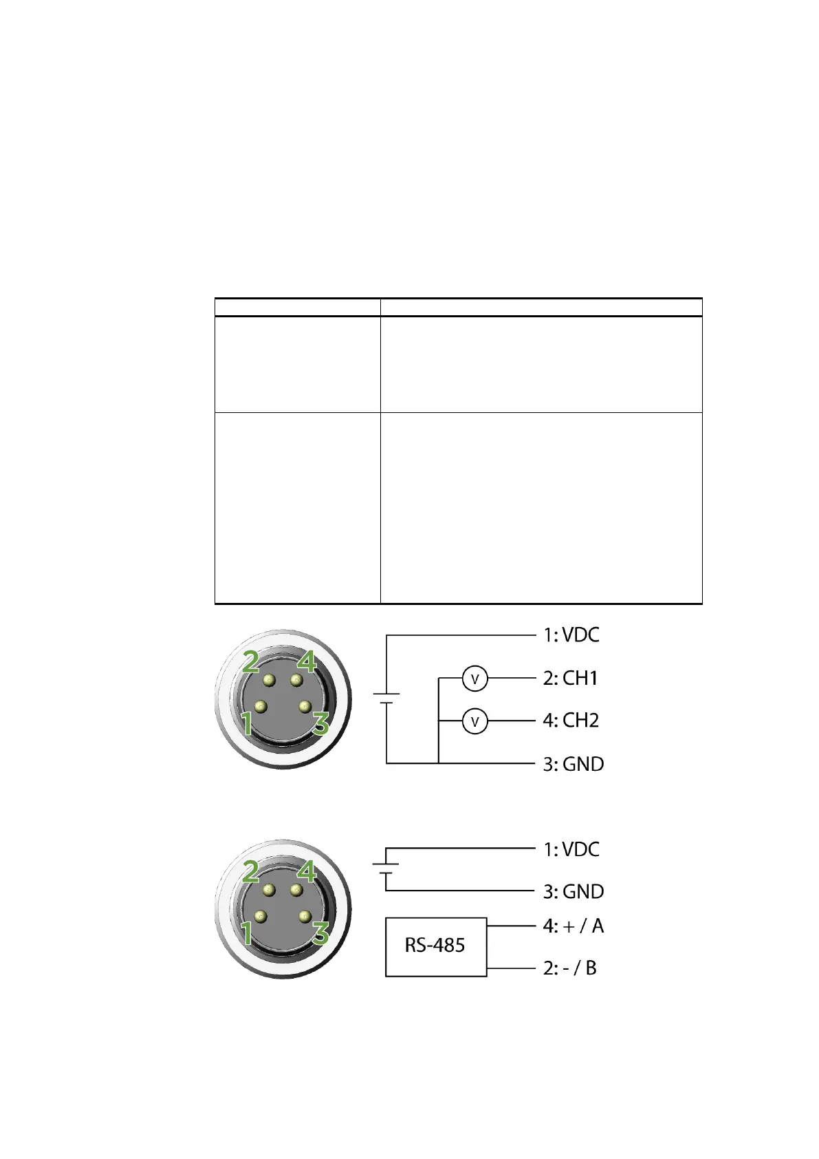
0912-104
Figure 20 Wiring of Analog Output
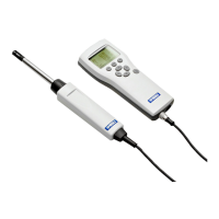
0912-105
Figure 21 Wiring of Digital Output