User's Guide _______________________________________________________________________
30 ___________________________________________________________________ M211060EN-H
Power Supply Requirements
The operating voltage for the HMP60 and HMP110 series probes must be
in the following range:
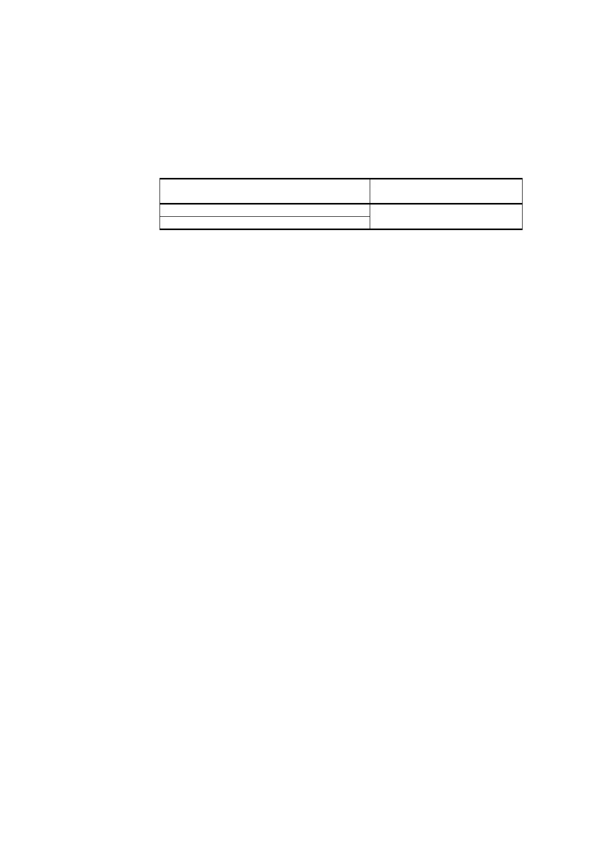
Table 7 Operating Voltage Ranges
HMP60 / HMP63 / HMP110 analog /
HMP113 / HMP110T
HMP110REF / HMP110 digital
5 ... 28 VDC (V
out
0 ...1 / 0 ... 2.5 V)
8 ... 28 VDC (V
out
0 ... 5 / 1 ... 5 V)
Current consumption is 1 mA on average, which makes the probes well
suited for running on battery power. The maximum peak consumption is
5 mA.
Recommendations
- Continuous use over high operating voltage may cause heating.
To conserve power and minimize the warming of the probe, use the
lowest operating voltage in the allowed range.
- Using low impedance loads on the signal outputs increase the current
consuption by up to 0.5 mA. High impedance loads are recommended
to minimize warming of the probe.
- Frequent interrogation of the probe using the RS-485 interface will
also increase current consumption from the average value. More
frequent interrogation than once per second is not recommended.