Chapter 3 ________________________________________________________________ Installation
VAISALA ________________________________________________________________________ 27
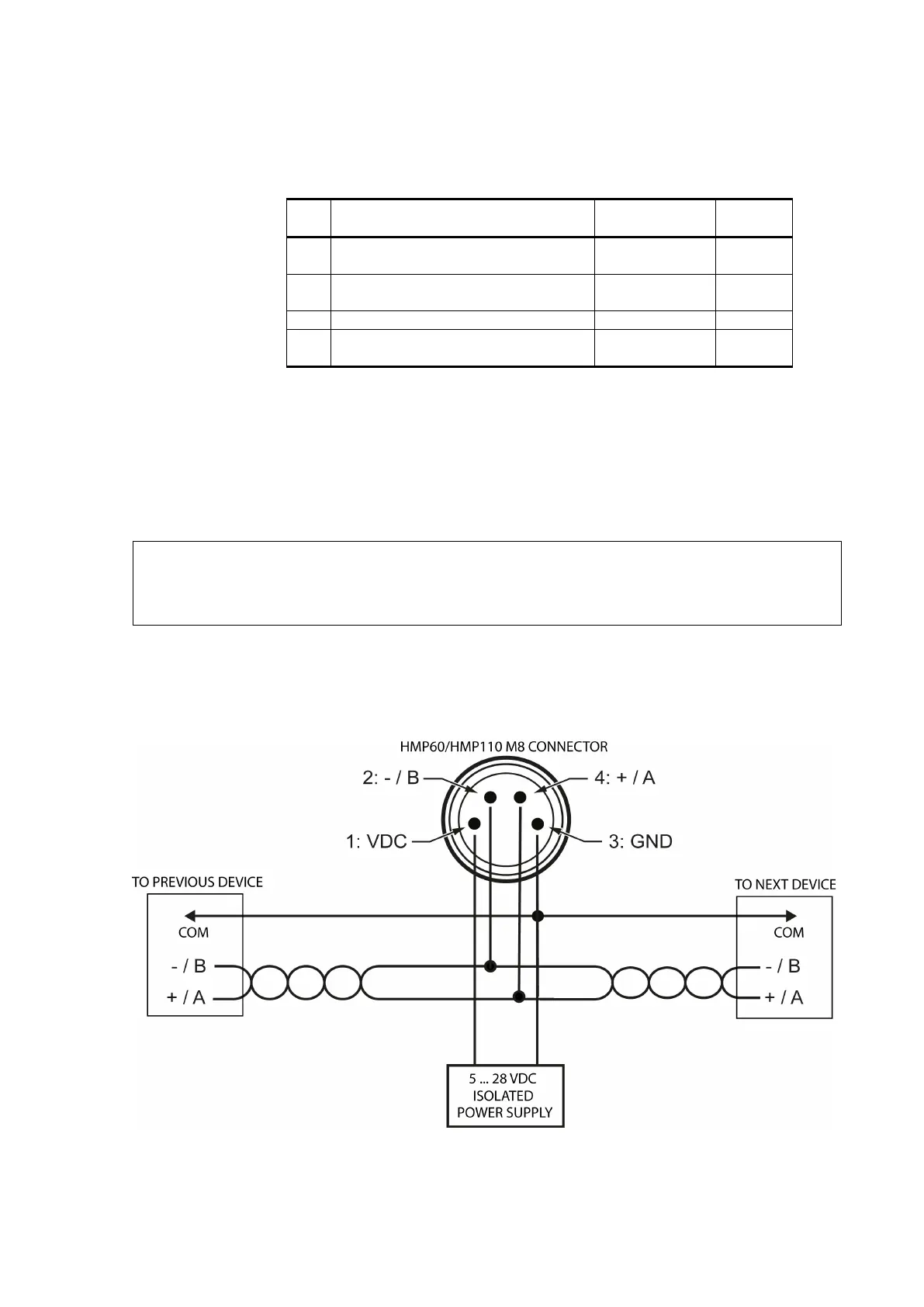
Table 6 Pinout of the Probe Connector
HMP60 / HMP63 / HMP110 analog /
HMP113 / HMP110T
HMP110REF /
HMP110 digital
out
0 ...1 / 0 ... 2.5 V)
8 ... 28 VDC (V
out
0 ... 5 / 1 ... 5 V)
Channel 1: RH / Td / T
0 ... 1 / 2.5 / 5 V, 1 ... 5 V
Channel 2: RH / Td / T
0 ... 1 / 2.5 / 5 V, 1 ... 5 V *
* HMP110T has no output on channel 2.
Wiring Multiple Digital Devices
The maximum number of HMP60/HMP110 probes that can be connected
to a system over the RS-485 interface is 32 when the communication
speed is 19200 bps or lower. RS-485 termination must not be used with
HMP60/HMP110 series probes.
NOTE
Connecting other devices can
decrease the maximum number of
60/HMP110 probes. If other devices require the use of termination,
60/HMP110 probes must be connected using an RS-485 repeater.
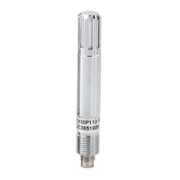
The following figures show the recommended wiring when connecting
multiple devices to the RS-485 interface using either a separate local
power supply for each device (see Figure 22 below) or a common power
supply (see Figure 23 on page 28).
1708-001
Figure 22 Wiring Multiple Devices Using Local Power Supply