807
REVO-E Heat pump 8 Removal/ installation of components (high-volt. syst.)
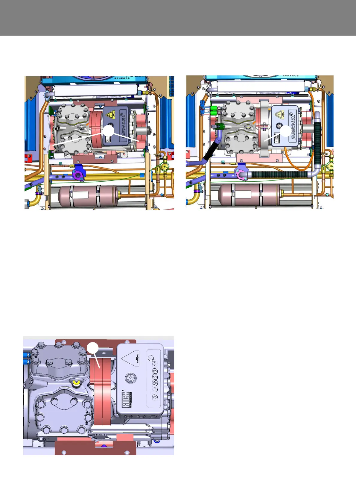
• Insert foam (4, Fig. 811) on both long sides in the
compressor pan and affix with compressor pres-
sure plate.
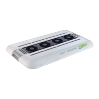
• Align foam (5, Fig. 812) on the upper side of the
compressor and reaffix compressor with mounting
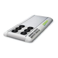
bracket (6, Fig. 813). Secure screw with sealing
wax against unauthorized access.
NOTE:
Please always comply with given torque. Other-
wise, the foam will lose its absorbent affect. This
causes the transference of vibration to the bus roof.
• Install mounting parts of the compressor in the
opposite order (Removing compressor, point 3.).
Use new seals when removing the refrigerant
cables.
• Lead the 400V AC cable through the opening in the
terminal box of the compressor.
• Connect the compressor to the electrical system
(see 6.5).
• Close the cap of the terminal box with the key.
Reattach the key to the compressor.
Fig. 811
Fig. 812
Fig. 813