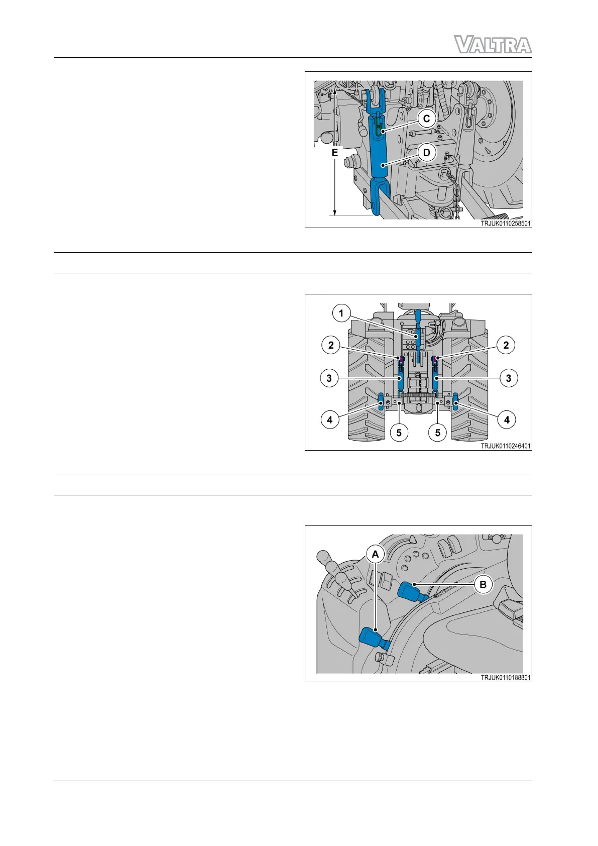
Lateral adjustment
To set the implement equally from side to side,
adjust the right or the left link rod:
• Lift the lock (C).
• Turn the link rod (D) clockwise to lift the
linkage.
• Turn the link rod (D) counterclockwise to lower
the linkage.
The length (E) must between:
• Minimum length = 430 mm
• Maximum length = 560 mm.
GUID-BBE7AE78-051E-4267-9281-54E7D99B19F5-high.jpg [High]
Fig. 103
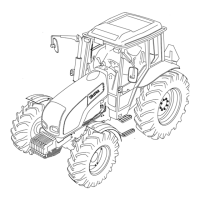
3.3.2 3 point hitch system
This linkage is made to category 2 specifications. It can be adapted to category 1 specifications.
(1)
Top link
(2) Lift arms
(3) Adjustable links
(4) Ball ends
(5) Lower links
GUID-181F4BB8-24E3-454E-AC8A-7BCC4A342CF1-high.jpg [High]
Fig. 104
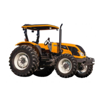
3.3.3 Hitch control levers
3 point hitch control levers
The position control lever (A) and the draft control
selector (B) adjust the position of the 3 point hitch.
IMPORTANT:
During transport and when the 3 point hitch is not
in operation, push the lever (B) fully forward.
The position control lever (A) lifts the 3 point hitch
when pulled rearward and lowers the 3 point hitch
when moved forward. The draft control lever (B)
controls the 3 point hitch position compared to
draft loads.
GUID-42CC8F35-EB29-4683-901E-B6694A031883-high.jpg [High]
Fig. 105
GUID-AB6451B1-5430-4A09-9E14-AFCE689C09A2 [V1]
GUID-EC11DC8C-138F-4BFF-88FA-9572B975EB92 [V1]
3. Operation
104 F Series
39940211 (555124)