Procedure
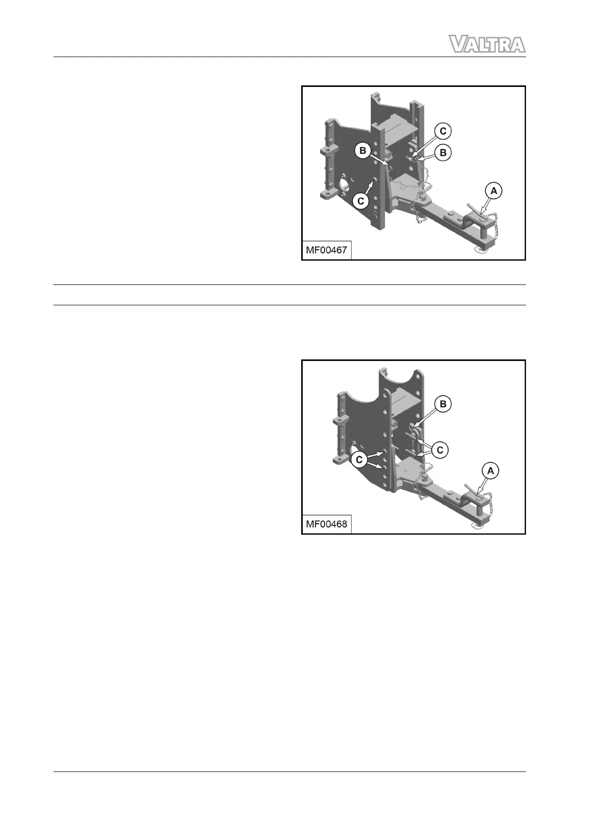
1. Support the swinging drawbar (A).
2. Remove the locking pins (B) and the side
pins (C) from each side.
3. Move the swinging drawbar (A) to the
required position and re-install the side pins
(C) and locking pins (B) removed.
NOTE:
Check and replace if needed worn or
damaged parts.
GUID-406EE309-10C5-40A0-80CC-DA1907866A0B-low.png [Low]
Fig. 136
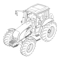
3.8.4 Adjusting the swinging drawbar height - models with holes guide rail
Tractors may be equipped with a swinging drawbar (A) with holes guide rail according with the options
available.
Procedure
1. Support the swinging drawbar (A).
2. Remove the locking pins (B) and the side
pins (C) from each side.
3. Move the swinging drawbar (A) to the
required position and re-install the side pins
(C) and locking pins (B) removed.
NOTE:
Check and replace if needed worn or
damaged parts.
GUID-4D334792-57C8-4E73-8A3B-04F9D23E486A-low.png [Low]
Fig. 137
GUID-DA56D118-19AE-4426-A144-715B47E19D28 [V2]
3. Operation
122 F Series
39940211 (555124)