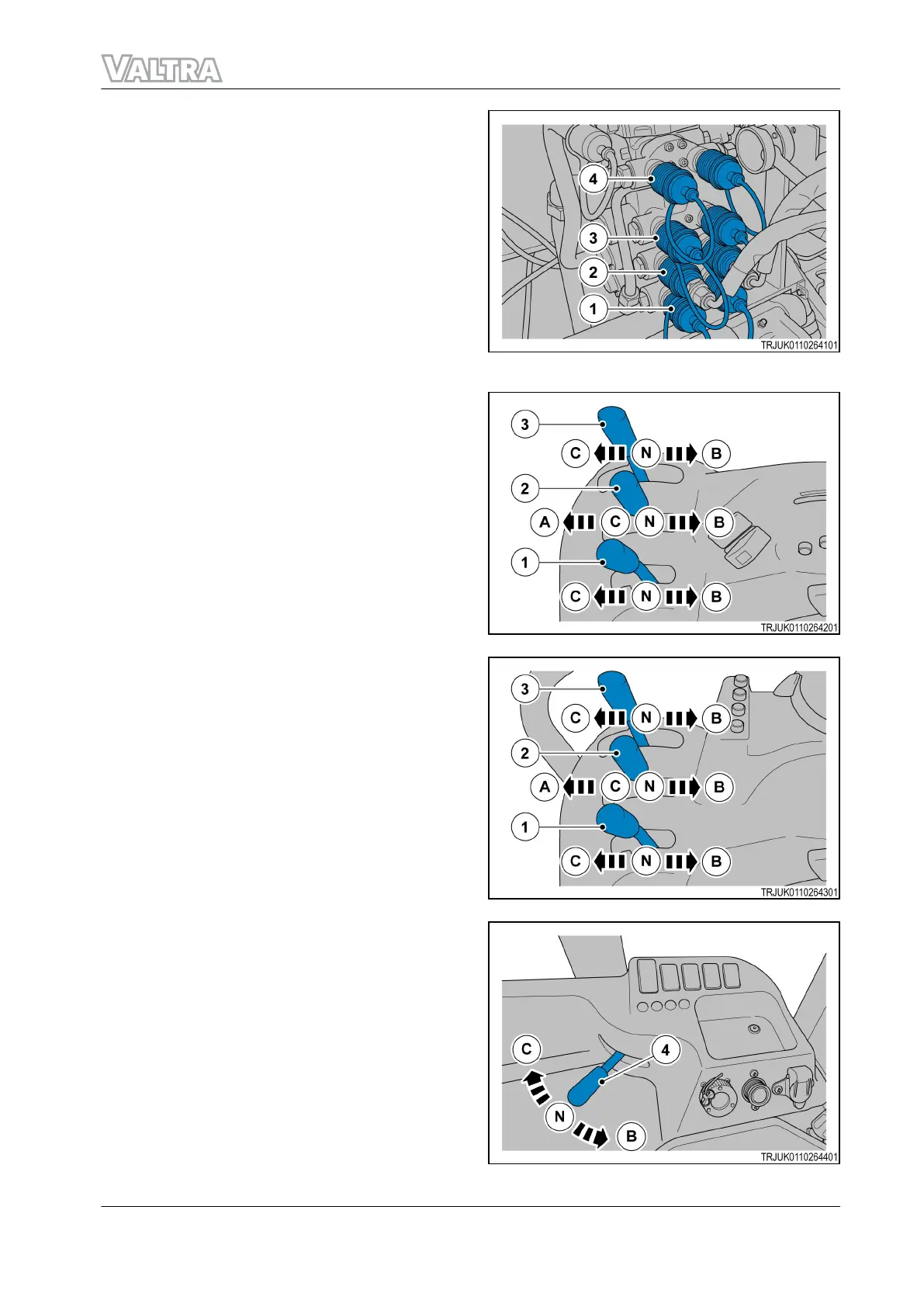
The hydraulic control levers operate the control
valves (1), (2), (3), and (4) in the rear of the
machine. For example, control lever (1) operates
control valve (1).
GUID-684452BC-9186-48C0-AB74-7157FF849FE0-high.jpg [High]
Fig. 115
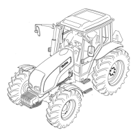
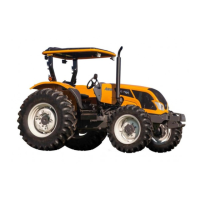
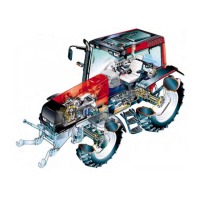
Positions of the levers:
N = neutral position
A = floating position
B = jack input position
C = jack output position
GUID-A6603E54-C2AB-481A-937A-989B450B5E98-high.jpg [High]
Fig. 116 With cab
GUID-8568693B-4947-47DB-A047-477053C30B03-high.jpg [High]
Fig. 117 Without cab
GUID-0510090B-535B-433B-BC20-A4EA67C4749A-high.jpg [High]
Fig. 118
3. Operation
F Series 109
39940211 (555124)