VAMP Ltd Generator protection relay
Operation and configuration
VAMP 210
VM210.EN004 Vamp 24h support phone: +358 (0)20 753 3264
33
Turns ratios of the voltage and current transformers:
Current transformer (CT) Inom 500 A
(Conf/current scaling) Isec 5 A
Voltage transformer (VT) Unom 6000 V
(Conf/voltage scaling) sec 100 V
U0sec 100 V
Core-balance current transformer I (CT) I01n 50 A
(Conf/Io1 scaling) t01sec 5 A
Core-balance current transformer II (CT) I02n 50 A
(Conf/Io2 scaling)
(not always used)
I02sec 5 A
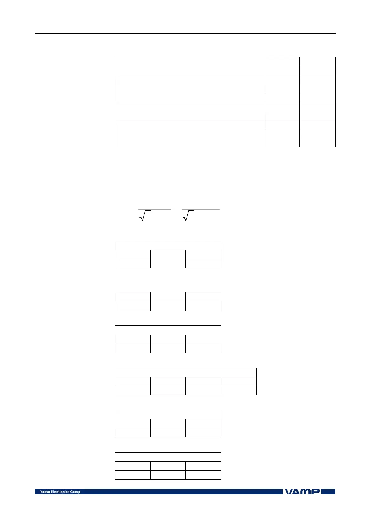
2 Calculation and selection of setting values:
The generator protection relay automatically calculates the
value of the rated current I
gn
of the generator from the set S
gn
and U
gn
values using the following expression:
A
kVa
U
S
I
gn
gn
gn
550
63003
6000
3
=
⋅
=
⋅
=
Overcurrent stage I> (51):
SET I>
I> k Type
1.20 1.50 NI
Overvoltage stage U> (59):
SET U>
U> t>
115% 3.00 s
Overvoltage stage U>> (59):
SET U>>
U>> t>>
140% 0.40 s
Undervoltage stage U1< (27):
SET U<
U1< t< NoCmp I<Blk
80% 10.00 s 20% 10.00 s
Reverse power stage P< (32):
SET P<
P< t<
-4% 2.00 s
Unbalanced load stage I
2
>:
SET I2>
I2 K1> Type
8% 20.00 s INV