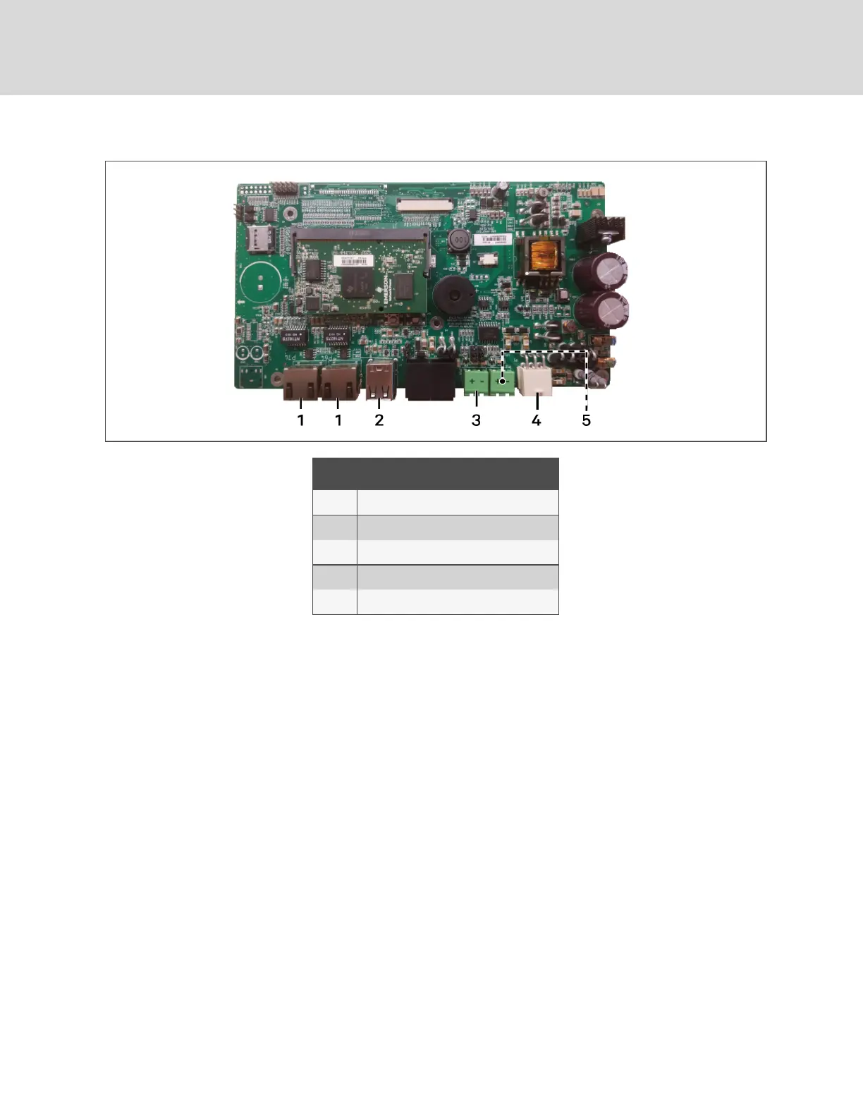
Figure 4.1 CMS Control-board connectors
ITEM DESCRIPTION
1 Ethernet port
2 USB ports
3 485 port for unit communication
4 24-VAC power input
5 485 port for BMS serial communication
4.2 Connecting the SRC andCMS ControlBoardswiththeModbusGateway
To communicate with a Liebert® SRC Mini-Split Cooling System, you must install a Modbus gateway that
connects the control board in the SRC evaporator/indoor unit and the iCOMCMS control board. Once
connected, the CMS control board can support up to 8 additional SRC units, by connecting gateways to
the units, and daisy-chaining the gateways together.
The Modbus gateway ships in its own box with the CMS kit. The Modbus gateway box includes the
following:
• Modbus gateway
• Black cable—to provide power and communication between the SRC board and the gateway.
• “Installation Manual V-Net”—instruction sheet to describe the connection between the SRC
board and the gateway.
Vertiv™ | Liebert® iCOM CMS™ Intaller/User Guide
36