4. Connect the black cable to the appropriate plug connections as shown in Figure 4.4 below:
• On the SRC control board: CN-CC plug connector.
• On the Modbus gateway board: CN-OUT plug connector.
5. Re-connect any plugs removed for access and re-insert the control board.
6. Lower the electric panel, and the top shell, reconnect the LED wires, install the bottom shell
and secure with the 3 screws.
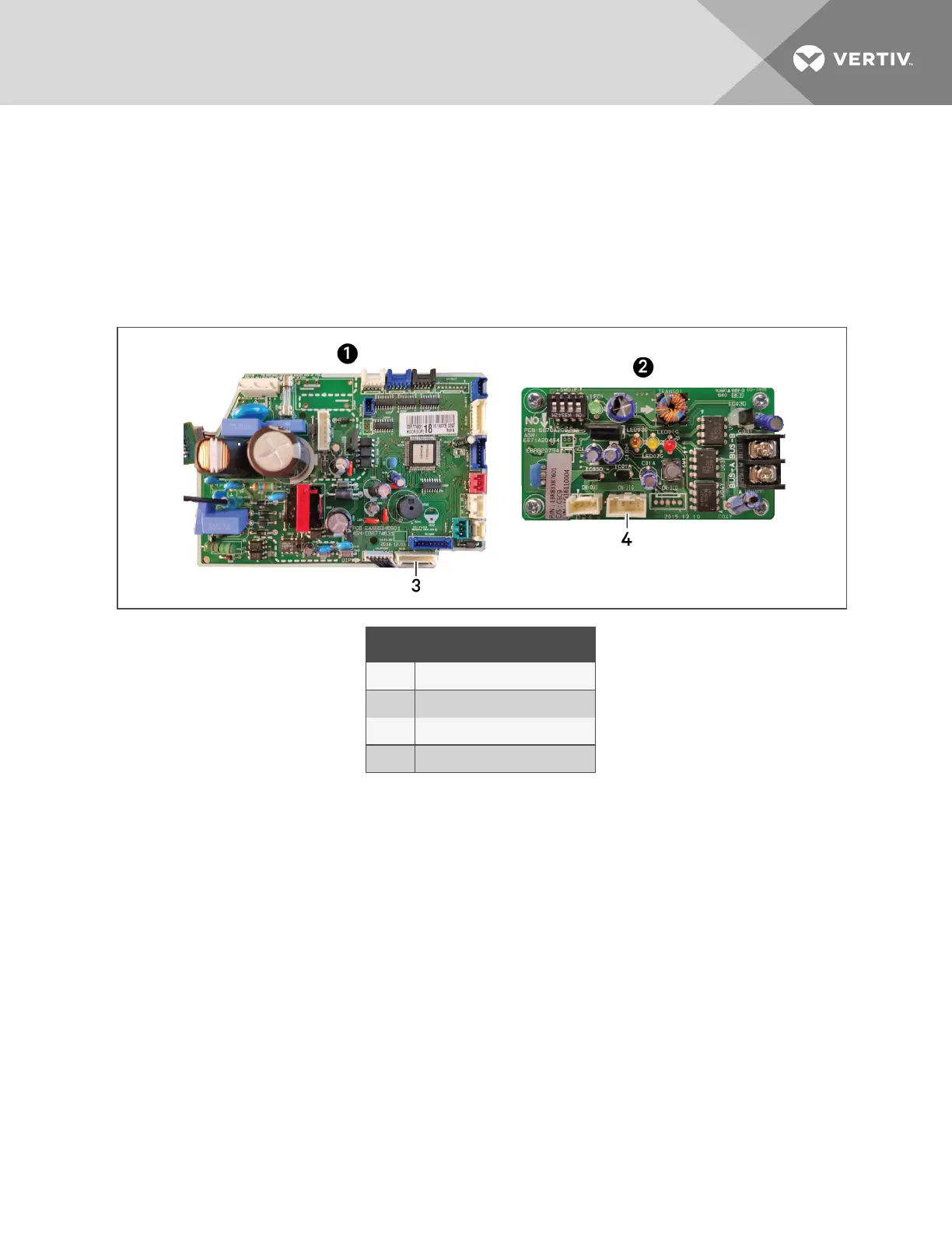
Figure 4.4 Connecting control board to Modbus
ITEM DESCRIPTION
1 SRC control board
2 Modbus gateway control board
3 CN-CC plug connector
4 CN-OUT plug connector
4.3 Setting up Communication withtheWeb-basedUserInterface
To register the thermal-management unit and configure communication settings, set-upaccess to the
control board.
NOTE: Only use the Google Chrome web browser to access the web UI.
1. Use a CAT5 Ethernet cable to connect a computer/laptop to an Ethernet port on the control
board (see Figure 4.1 on page36).
2. Configure the computer to communicate with the control board by changing its network
settings as follows:
• Set the computer’s static IP address to: 169.254.24.10
• Set the computer’s subnet mask to: 255.255.0.0
4 Installing and Connecting iCOMCMS
39