38
Vertiv I Liebert LPC I User Manual
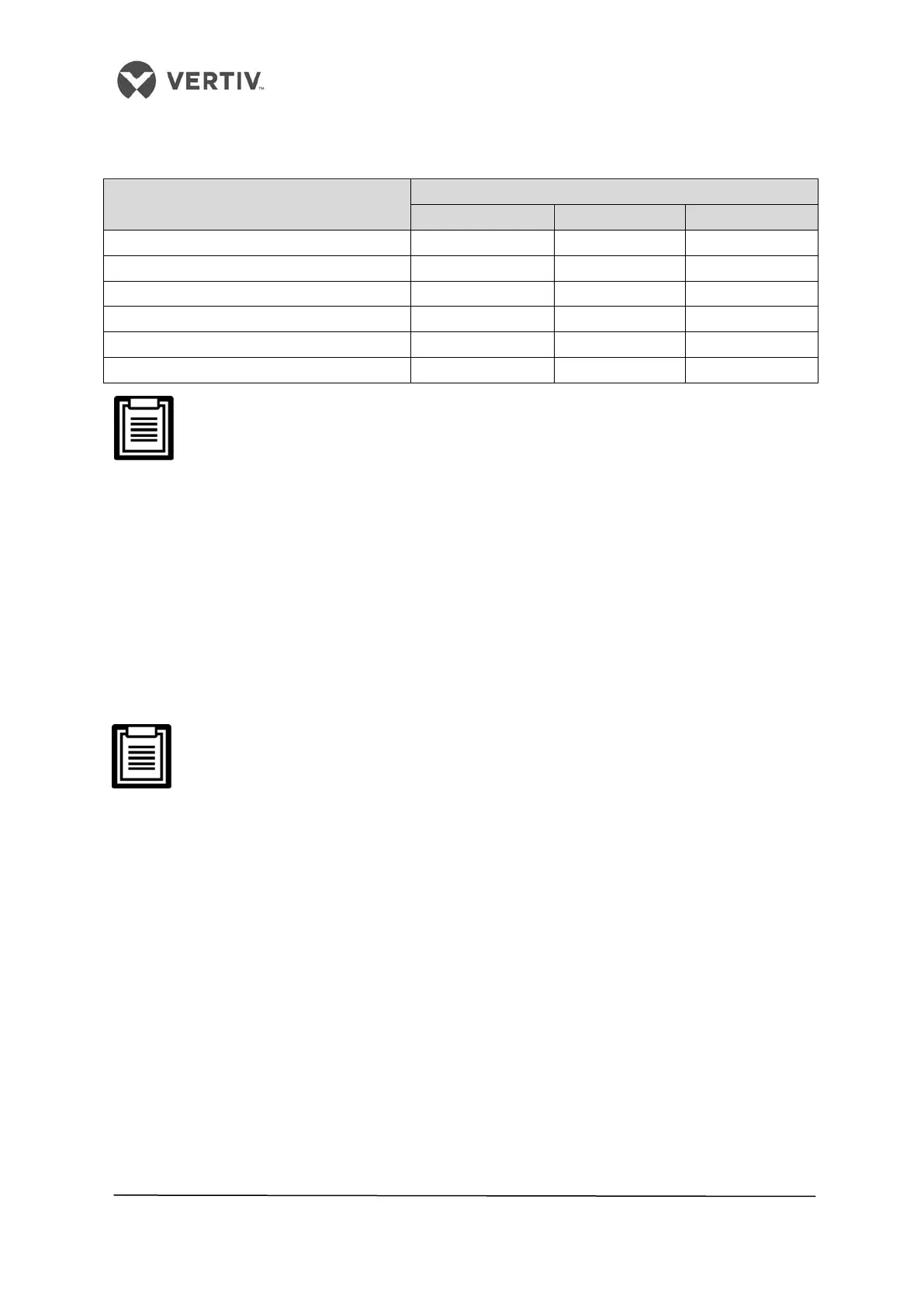
Table 2.8
• Equivalent length of the partial components
Outer diameter (OD) of the liquid pipe
(inches)
Equivalent length (meters)
90° bend 45° bend T Type 3-way
3/8 0.21 0.10 0.76
1/2 0.24 0.12 0.76
5/8 0.27 0.15 0.76
3/4 0.3 0.18 0.76
1-1/8 0.56 0.3 1.4
A trap must be installed every 7.5m of the vertical distance. Please consult Vertiv
Co. for inquiry and installation.
• Vertiv Co. recommends the installation of the solenoid valve onto the outdoor
project pipe of the ball valve on the liquid pipe to avoid the opening of the pipe
during the installation of the pipe extension kit.
• Installation can be done on the outer side or the bottom of the unit. Therefore, there
is no necessity of cutting the indoor unit pipes while installing the solenoid valve.
• Once the entire system is installed, open the ball valve to keep the pressure and
carry out the vacuum operation. This avoids the moisture absorption of the
compressor refrigeration oil. This accounts for operation safety in addition to
extending the life of the compressor.
For electrical connections related to the pipe extension kit, refer to the Electrical
installation section.
Following are the steps that need to be implemented in the installation procedure of the
Solenoid valve in the liquid pipe:
1. The solenoid valve must be as close to the indoor unit as possible. The valve body
and coil of the solenoid valve are separated when the valve is shipped out.
2. Mount the valve body horizontally in the refrigerant pipe as shown in Figure 2-22. Pay
attention to the arrow on the valve body as the arrow indicates the flow direction of
the refrigerant in the valve. Ensure that the arrow points towards the indoor unit.
 Loading...


