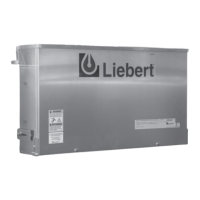
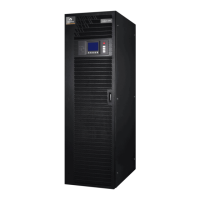
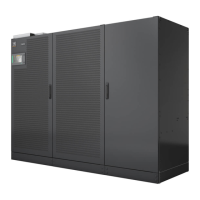
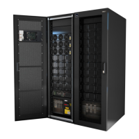
OPTIONS Liebert Trinergy™ Cube
Installation Manual - 10H52243IM60 - rev. 7 - 06/2020 Page 123
6. OPTIONS
Some of the options listed in this section may modify the data on the standard technical data tables (see
“Technical data - CORE” on page 129 and “Technical data - SYSTEM” on page 131). It may not be possible
to use certain options simultaneously on the same UPS.
6.1. MBSM (up to six UPS)
The MBSM is a device which is basically intended to provide a frequency reference signal (spit over a
certain number of channels = normally six) on its outputs. This signal is a square wave generated by an
incoming source reference or by an internal quartz. Each UPS connected to the MBSM is able to receive
the frequency reference signal and, under particular conditions, to automatically phase lock the inverter.
Each UPS in the system is supplied by a common electrical bus; per default, the UPS synchronization
source (reference) is the power source connected on its reserve input and, as a consequence and
because the power source is common to all the UPS, the inverter outputs will be in synchronism.
If the main power (reserve inputs) should fail, each UPS will synchronize the inverter to the signal coming
from the MBSM (Fref.) and, as a result, the inverters are still in synchronism.
If the Fref. is not available (or the MBSM is not installed), each UPS will synchronize the local internal
quartz, therefore the inverter outputs would be, in this case, asynchronous.
It is than clear that the MBSM has a simple PASSIVE role in relation to the UPS. With the maximum level
of independence, the UPS will determine the source of synchronization on the basis of the following
priority scale:
HIGHEST PRIORITY = LOCAL RESERVE INPUT
MEDIUM PRIORITY = MBSM REFERENCE
LOWEST PRIORITY = LOCAL QUARTZ OSCILLATOR
For installations and operations please consult the MBSM User Manual.
6.2. SYNCHRO BOX FOR UPS
This device has been designed for use in complex power source systems, consisting of different
distribution and CROSS switches supplied by Vertiv and other manufacturers. It provides
synchronization between Vertiv Liebert Trinergy
TM
Cube, 80-NET and 90-NET UPS and third-party
systems, when it cannot be guaranteed by the system configuration or when temporary conditions
prevent it (e.g. during battery operation).
Examples of configurations where the External Sync. Box can be used:
• Installation consisting of two Vertiv systems;
• Installation consisting of Vertiv systems and electrical generating devices;
• Installation consisting of Vertiv and third-party systems.
The device operates by identifying one of the connected units as the master and using its frequency as
a reference for the other units (slaves). While other brand UPS can be used as the
master, only Vertiv UPS can be used as slave units.
Depending on their configuration, the slave units will follow the reference frequency all the time, or only
when their reserve mains supply is out of tolerance.
The reference frequency will be generated only when the master mains supply line is within acceptable
limits.
The device can drive up to two separate units, which may be independent of one another, or
connected together in a parallel system: where the installation consists of more than two slave
units, or the master/slave configuration is not the preferred option we advise using the Vertiv Multi Bus
Synchronization Module (MBSM).
For installations and operations please consult the Synchro Box User Manual.
6.3. KIT I/O BOX Liebert Trinergy
TM
Cube MODBUS
The Modbus RTU/JBus and Modbus TCP option enables Liebert Trinergy™ Cube to be connected to a
field bus for bi-directional communication between numerous devices. The Liebert Trinergy™ Cube
Touch Screen acts as communication protocol converter between the UPS and the Modbus master.
Hence Liebert Trinergy™ Cube can be accessed via the Premises LAN RJ45 connection through the
customer Modbus system. The Modbus Service menu is used for Modbus service settings.
 Loading...
