Liebert Trinergy™ Cube Electrical INSTALLATION
Page 84 Installation Manual - 10H52243IM60 - rev. 7 - 06/2020
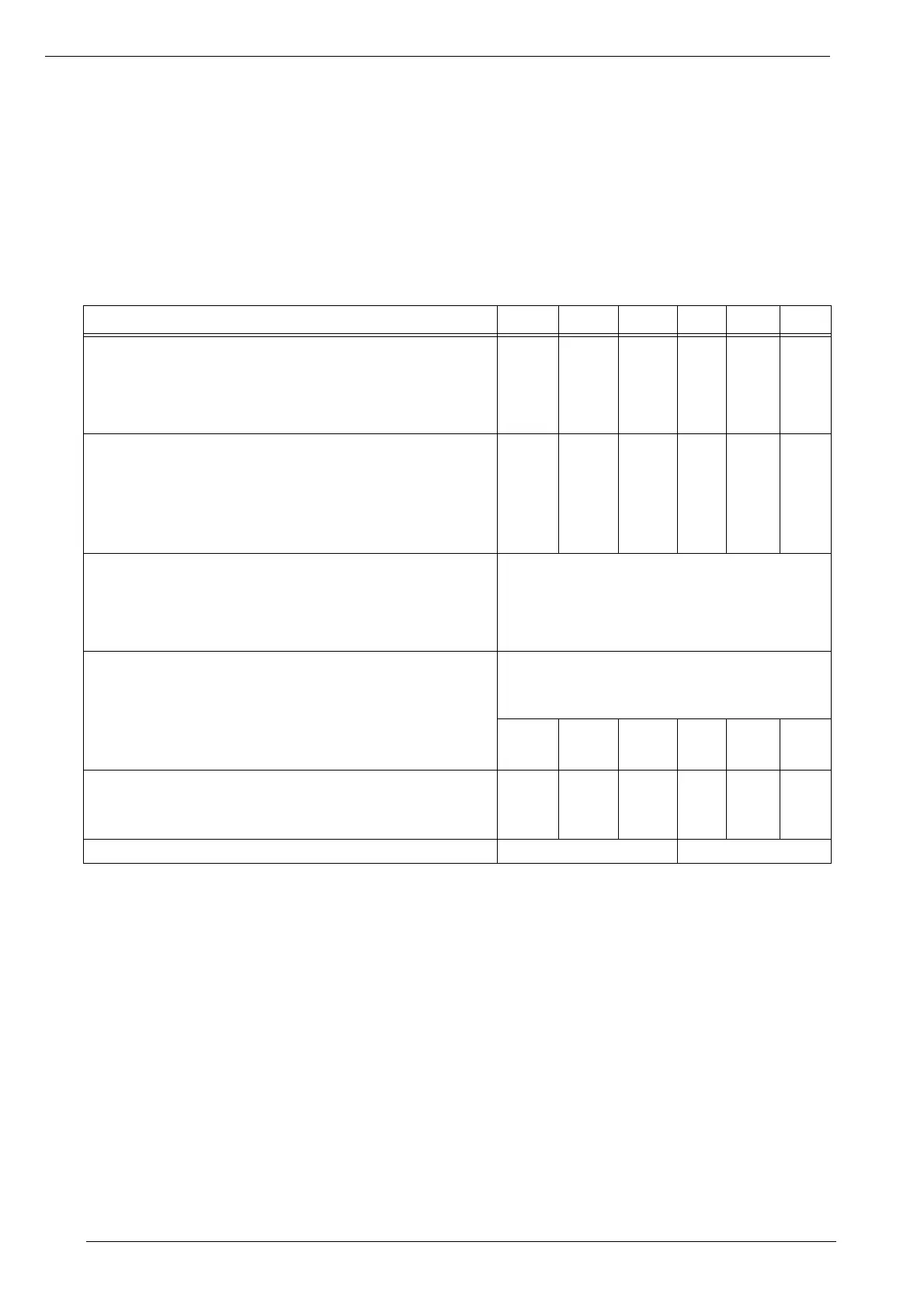
4.6.1. UPS output line
Since load(s) can be supplied through the Uninterruptible Power System from two sources, the ratings
of the following supplies should be taken into account when designing the output line protection system.
If a single differential breaker is installed ahead of the UPS, any fault in the installation grounding system
will result in the interruption of power to both the line power input and the direct line.
The data in this table refers to the maximum current and power handled by the box and the maximum
number of cores connected.
If a system has a lower number of CORES (thus with available power lower than the I/O BOX rating), the
cables can be sized according to the real current and power handled by the system.
Table 2 UPS Nominal Current
I/O BOX rating (A) 600 1200 2400 3000 4000 5000
Primary Power line
Max. current (A)
1)2)
Max. number of conductors connectable to I/O BUSBAR
& cross section (mm
2
)
1) For a nominal voltage of 380V, multiply the current value by 1.05; for 415V, multiply by 0.96. The maximum current is the same
regardless of nominal voltage.
2) Overload current specified in para. 8 on page 129 must be considered.
630
1x240
1250
2x300
2500
4x300
3200
/
4250
/
5000
/
Bypass Power line/Load
Nominal current (A)
2)
Max. current (A)
2)
Max. number of conductors connectable to I/O BUSBAR
& cross section (mm
2
)
577
635
1x240
1155
1270
2x300
2309
2540
4x300
2887
3175
/
3464
3811
/
4619
5081
/
Battery, external +, -
Max. current (at 1.8V/cell - 240 cells) (A)
3)
Max. number of conductors connectable to I/O BUSBAR
& cross section (mm
2
)
4)
3) To select the cross section, see the actual installation data and national and local codes. Number and cross section of battery
conductors can be sized for a maximum continuous current at 1.8V/cell and a maximum voltage drop of 2.0Vdc at 1.67V/cell
EOD.
4) Power cable from module DC bus to battery should be sized for a total maximum 2.0 volt line drop (power cable drop plus return
cable drop as measured at the module) at maximum discharge current.
868
2x300
Neutral (N) from line power/ to load N, N2
Coefficient for oversizing the neutral line conductor
when non-linear load is supplied
1
Max. number of conductors connectable to I/O BUSBAR
& cross section (mm
2
)
5)
5) Grounding conductors and neutral conductors to be sized per 60364-5-54:2011 and per national wiring standards.
2x240 4x300 8x300 / / /
Earth
Max. number of conductors connectable to PE BUS-BAR
(mm²)
5)
1x240 2x300 4x300 / / /
Type of connector
BUSBARS FLANGES
 Loading...