Liebert Trinergy™ Cube Technical data - CORE
Page 130 Installation Manual - 10H52243IM60 - rev. 7 - 06/2020
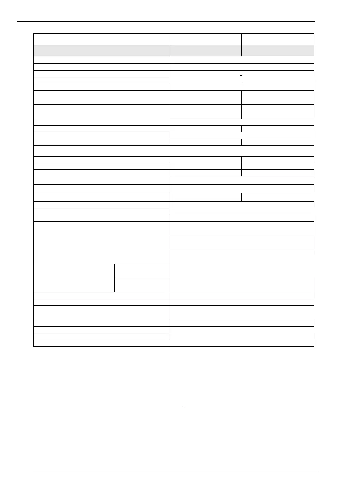
VRLA float voltage temperature compensation (%) -0.11 per °C
Float mode DC ripple for 10 min. autonomy as per VDE0510 <0.05C
10
Float voltage stability in steady state (%) <1
DC ripple voltage without battery (%) <1
Optimum battery temp. (°C) 15 to 25
Battery recharge current setting range for 240 cells @ nominal
load (A)
Up to 18 Up to 37
Battery recharge current setting range for 264 cells @ nominal
load (A)
Up to 17 Up to 34
End of discharge voltage with 240 cells (1.65 V/cell) (V) 396
Battery current @240 cells, 1.65V/cell, 20°C (A) 526 1051
End of discharge voltage with 264 cells (1.65 V/cell) (V) 436
Battery current @264 cells, 1.65V/cell, 20°C (A) 477 955
Output
Nominal apparent power lagging or leading load PF (kVA) Up to 200 Up to 400
Nominal active power (kW) Up to 200 Up to 400
Nominal output current (A) 290 577
Overload at Vout nom. for 5 min. (%)
7)
125
Overload at Vout nom. for 1 min. (%)
7)
150
Short circuit current for 200ms (A)
8)
650 1300
Nominal output voltage (Vrms) 400 (3ph + N + PE) or 400 (3ph + PE)
Selectable output voltage (Vrms) 380, 400, 415, 440
Nominal output frequency (Hz) 50 (60 selectable)
Voltage stability in steady state condition for input variations (AC
& DC) and step load (0 to a nominal load) (%)
±1
Voltage stability in dynamic condition for i/p variations (AC & DC)
and step load (0 to a nominal load and vice versa)
Complies with IEC/EN 62040-3, Class 1
Voltage stability in steady state with nominal load imbalance (0, 0,
100) (%)
±3
Output frequency stability
Synch. with bypass line
power (%)
±2 (2, 3, 4, 5 selectable)
Synch. with internal
clock (%)
±0.1
Frequency slew rate (Hz/s) <1 default (selectable up to 5Hz)
Output voltage distortion at 100% nominal linear load (%) <1.5
Output voltage distortion @ ref. non-linear load as per IEC/
EN62040-3 (%)
<5
Max Load Crest Factor without derating (Ipk/Irms) 3:1
Phase angle accuracy with bal. loads (degrees) ±1
Phase angle accuracy with 100% unbalanced loads (degrees) ±3
Neutral conductor size 1 x nominal current
1) Due to the UPS smart capacity feature the Core rating is dynamically set according to the ambient temperature at the UPS
installation site, thus the maximum available output power limit is changed accordingly. Please see user manual and product
documentation for further details.
2) Nominal input voltage and input frequency.
3) For tolerances see IEC/EN 60146-1 or DIN VDE 0558. The data refers to 25°C ambient temperature tested with battery
disconnected as per IEC/EN 62040-3.
4) The efficiency rating refers to the UPS when it is in VFI mode with circular redundancy.
5) Referred to derated load conditions. For additional information, contact the technical support.
6) With input voltage at nominal value and voltage distortion THD
v
< 1%.
7) Value obtained at 25°C ambient and input voltage at nominal value. Depending on the load level in kW the maximum rectifier
input current maybe reached, in this case a portion of the power to critical load is fed from the battery. Overload is a stressful
condition for the semiconductors and an ageing factor, and therefore cannot be repetitively performed in a limited amount of
time
8) Short circuit current is effected by short circuit impedance. Value report in the table assumes a neglectable low impedance in
the short circuit path.
CORE
Rating (kVA) 125-200
1)
250-400
1)
 Loading...