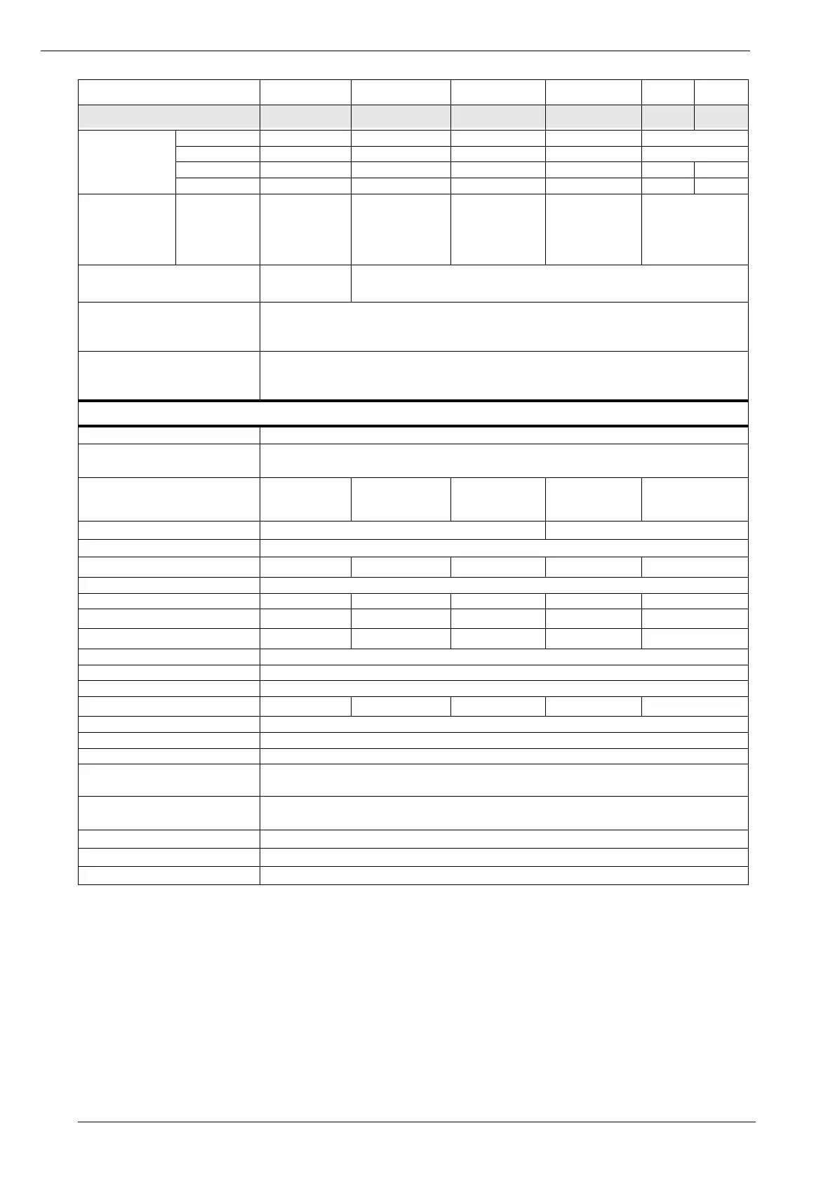
Liebert Trinergy™ Cube Technical data - SYSTEM
Page 132 Installation Manual - 10H52243IM60 - rev. 7 - 06/2020
Overload
capacity
4)
10 min. (A) 875 1750 2580 5150 6250
1 min. (A) 1430 2860 4180 6960 6450
600 ms. (A) 4000 8000 16000 22000 32500 32500
100 ms. (A) 7000 14000 24000 36000 57000 57000
Bypass fuse rating
pre-arc
5)
I
2
t (kA
2
s)
1000A, aR class
I
2
t 180kA
2
s
(@400V)
prearc 630kA
2
s
1250A, aR class
I
2
t 860kA
2
s
(@400V)
prearc 355kA
2
s
2x1250A, aR class
I
2
t 3440kA
2
s
(@400V)
prearc 1420kA
2
s
2x1600A, aR class
I
2
t 4300kA
2
s
(@400V)
prearc 1220kA
2
s
5000A, aR class
I
2
t 19000kA
2
s
(@400V)
prearc 5450kA
2
s
Prospective short circuit current
Icp
6)
(kA)
50 100
Inverter to bypass and bypass to
inverter transfer time with inverter
synchronized with bypass
No break
Default transfer delay time (inverter
to bypass) with inverter not
synchronized with bypass (ms)
<20
Box data
Protection degree with doors open IP20
Mechanical dimensions Core Disc.
(mm)
350x910x1950
Mechanical dimensions I/O BOX
(mm)
800x910x1950 1275x910x1950 1450x910x1950
1450x910
7)
x1950
1300x910
7)
x1950
1950x910
7)
x1950
1950x910
7)
x1950
Number of cabinets 1 2
Frame color (RAL scale) 7021
Shipping Weight I/O BOX (kg)
8)
720 1130 1415 1370+1270 2270+1315
Net Weight Core Disc. (kg) 140
Net Weight I/O BOX (kg) 660 1050 1295 1250+1150 2170+1215
Floor area (m
2
)
0.74 1.18 1.34 1.34+1.20 1.80+1.80
Floor load (kg/m
2
)
892 890 967 933+958 1206+675
Cable entry Top/Bottom
Service Access Front/Top
Cooling system Forced ventilation, front air intake, top air outlet
Air flow (m
3
/h)
630 1100 2200 3300 5500
Location Indoor (free from corrosive gases and conductive dust)
Operating Temperature (°C) 0-55
Transport and storage (°C) -20 to +70
Max. relative humidity up to 35°C
(without condensation) (%)
0% to 95%, maximum non-condensing for operation and storage
Max. altitude above sea level
without derating (m)
Up to 1000 above M.S.L. (at higher altitudes, unit complies with IEC/EN 62040-3)
Immunity to electrical interference IEC/EN 62040-2
EMC CLASS IEC/EN 62040-2 Class C3
AC Power distribution TT, TN-C, TN-S, IT
1) Nominal load.
2) Maximum configuration of CORES.
3) See CORE technical data, para. on page 130 for Inverter data.
4) It is assumed to supply steady state load @100%, after the over load is applied. In case of different levels of overload, see the
specific overload curve. For additional information, contact the technical support
5) I/O BOX 600-1200A uses one fuse per phase, all other I/O BOX use two fuses in parallel per phase.
6) Value stated for static bypass with internal fuse protection.
In case of system configuration with maintenance bypass included the fuse protection shall be externally fitted for this line.
For additional information, contact the technical support.
7) In the back-to-back configuration, which is suggested as preferential, a structure is provided to permit the optional installation
and connect the back of the STS BOX to the back of the I/O BOX properly, but it is not shown in this manual.
8) Core disconnectors are shipped connected to the I/O Box or STS cubicle.
BOX model
Rating (A) 600 1200 2400 3000 4000 5000
 Loading...