9
Original Operating Instructions: K4 edition
Document version: E – 02/2020
Machine description
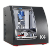
3.3 Working chamber
The machine processes all blanks in the working chamber.
1
2
5
4
3
[1] Spindle
[2] Tool magazine for up to 7 tools
[3] Measuring key for measuring the tool length
[4] Blank holder and rotational axis A
[5] Collet chuck for picking up tools
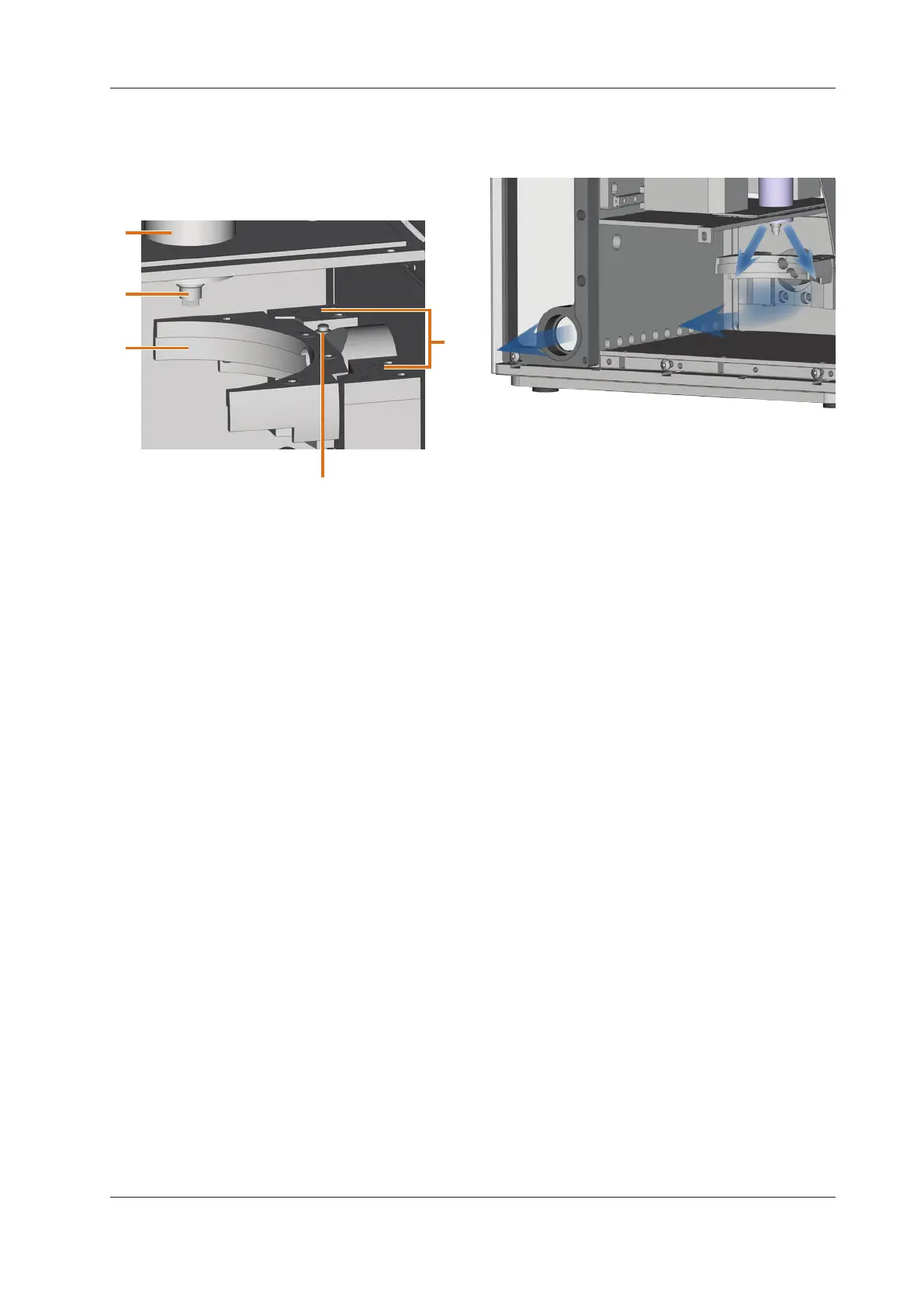
3.4 Air extraction concept
The air extraction concept consists of:
The sealing air of the spindle
The external air extraction system (suction device,
suction hose, optional switching unit)
The vacuum sensor
During job execution, the spindle constantly blows air into
the working chamber (
Fig. 5, upper arrows)
An external suction device that you connect to the Machine
with a suction hose extracts the machining debris from the
working chamber (
Fig. 5, lower arrow).
This concept decreases the soiling and wear of sensitive ma-
chine parts.
n
The air extraction system does not replace the regular
cleaning of the machine. Without regular cleaning, the
machinelifedecreasessignicantly.
Through the air extraction, a vacuum develops in the working
chamber which is constantly monitored by a vacuum sensor
(display in DentalCNC:
chapter 4.8, page 17). If the vac-
uum is too weak, machining is not possible. If the vacuum
becomes too weak during a running job, DentalCN
C inter-
rupts
machininguntilthevacuumissucientagain( chap-
ter
5.7, page 20).
The current strength of the vacuum displays in DentalCNC
(
chapter 4.8, page 17 or in documentation for the man-
ufacturing software).
3.5 Manufacturing software and CAM computer
To operate the machine, you must use a computer running
Windows® (“CAM computer“) which should connect to the
machine via the provided USB cable.
You can process manufacturing jobs with the CAM computer
in 2 steps:
1. With DentalCAM you can create jobs with the objects
that you want to machine. DentalCAM already contains
allimportantparametersforthedierentmaterials.
2. You can execute the jobs with the CNC software
DentalCNC. This application oers additional mainte
-
nance and control functions for the machine.
b
You must use a dierent computer together with a
scanner and suitable software to create 3D models of
the objects (not provided, sold by specialist dealers).
3.6 Sound emission
The actual sound emission of the machine varies heavily de-
pending on the manufacturing material and the machining
conditions.
h If the machine is too loud, check the operating condi
-
tions. Ensure that the blank
isxedproperly,checkthe
condition of the tool and the material in use.
h If loud noise cannot be avoided, wear ear protection
during machining.
Sound measurement
Measuring conditions:
Processed material: CoCr
Tool status: new
Distance to sound source: 1 m
Measurement according to ISO 3746, engineering
method 3