15.5. Garnet SeeLevel II 709-RVC & Victron GX device support
With RV-C support in Venus OS it is also possible to use the Garnet SeeLevel 709-RVC and display its data on the GX device
and VRM. All 709-RVC models and the SeeLevel Soul are compatible with the GX.
Note the limitations as described in the Limitations section [96]. This means that when using a CAN-bus port on the GX device for
RV-C, it cannot be used for other purposes at the same time, such as the common VE.Can and NMEA 2000 features. It's either
VE.Can/N2K or RV-C, unless it's a Venus GX which has two full VE.Can ports. If this limits further use of the GX device too much
in terms of connectivity via VE.Can, it is recommended to use the Garnet SeeLevel 709-N2K instead.
Also note that tank levels displayed on the Victron GX will be in percentage, not actual volume in liters, gallons, or any other unit
of volume.
15.5.1. Wiring the Garnet SeeLevel II 709-RVC tank level sensor to a GX device
Before connecting to a GX device, ensure that the Garnet SeeLevel 709-RVC has been installed and configured correctly
according to Garnet's installation instructions.
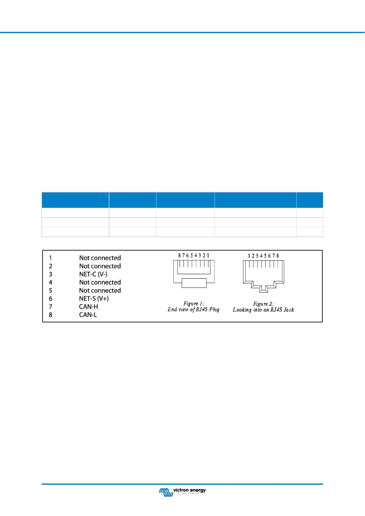
While the VE.Can port requires an RJ45 connector, the Garnet SeeLevel panel features either a multi-pin RV-C connector or
wired connection with one black, one blue and one white wire each. In order to be able to connect both together, an adapter cable
must be built according to the pin assignment in the table below.
A commercially available CAT5 Ethernet cable is best suited for this, whereby one of the two ends is first cut off and then
connected to the Garnet panel.
Garnet panel wire
colour code
RV-C connector Victron VE.Can
RJ45
CAT5 Ethernet wire colour
code
Signal
Black 4 3 green/white Ground
Blue 3 8 brown CAN-L
White 2 7 brown/white CAN-H
Victron VE.Can pinout
15.5.2. Installation and configuration
1. Route the cable from the Garnet panel to the GX device.
2. Make sure both the Garnet and the GX device are powered off.
3. Connect the RJ45 plug to the VE.Can port of the GX device and the other end of the adapter cable to the Garnet panel.
4. Make sure the bus termination is correct. For the GX device: Use the included blue VE.Can RJ45 terminator. Proper bus
termination is mandatory for the Garnet SeeLevel if it is the only RV-C device.
5. Once everything is installed correctly, turn on both devices.
6. Proceed with the RV-C configuration as explained in the RV-C Configuration chapter to properly configure the VE.Can port for
the RV-C profile.
Color Control GX Manual
Page 99 RV-C Support

 Loading...