SHB 28Z3 EN – Edition 2.0 * 28z3s410.fm 4-11
Engine
☞ Then slowly turn back approximately two more rotations until about 20° before top dead
centre.
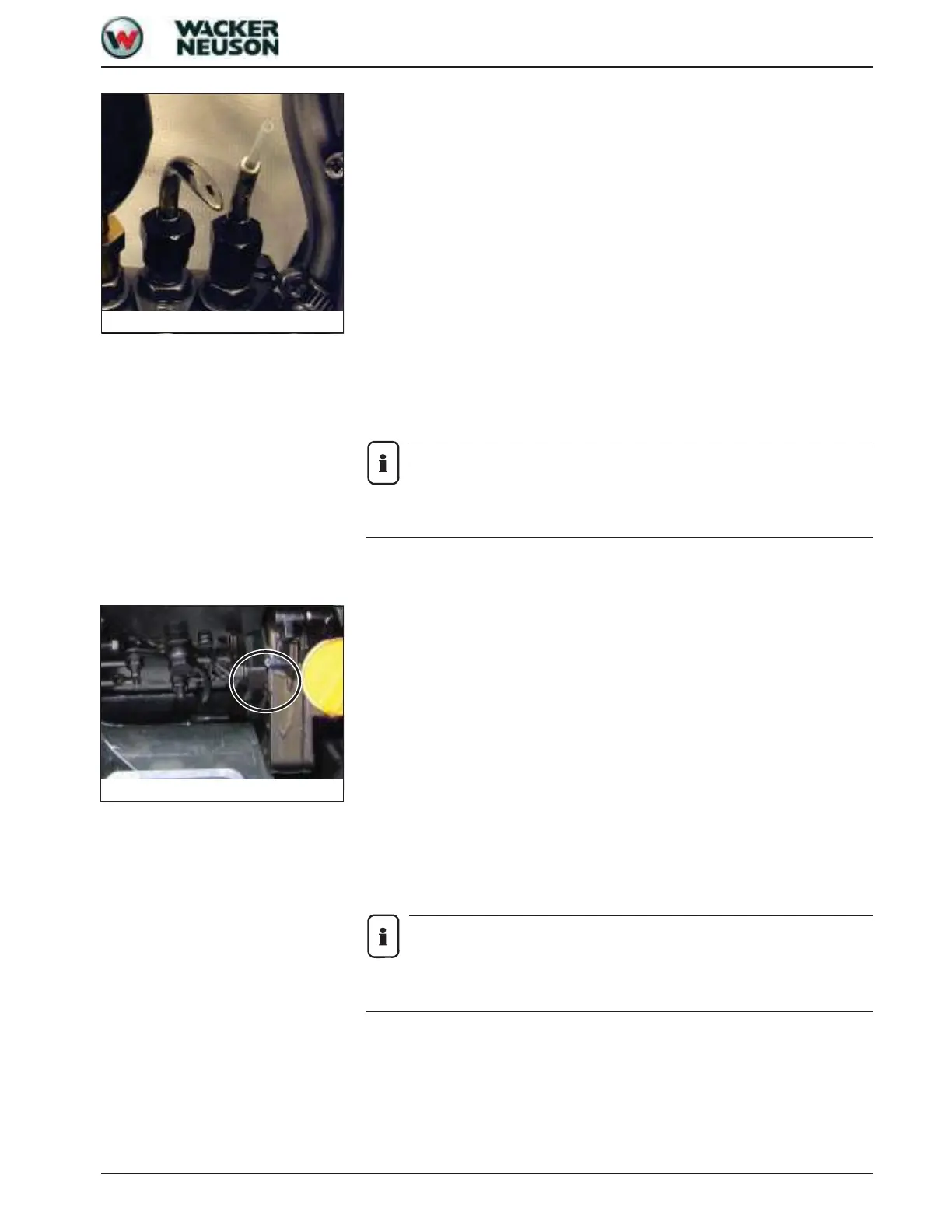
☞ Remove any bubbles at the opening of the injection pump with your finger so that the
opening of the injection pump is about half full with fuel
☞ Slowly keep turning the crankshaft clockwise until the fuel level rises to the opening of
injection pump A
☞ Stop the rotary motion immediately
☞ Read the degrees before top dead centre by means of the indentation on the flywheel
➥ Rated value: 16° +/- 1° before top dead centre – see Marks on flywheel on page 4-
10
☞ Measure the injection time two to three times
➥ If the specified value is reached, the injection time is correct
☞ Refit the fuel injection line, cutoff solenoid and cap
☞ Check the fuel system for leaks
➥ If the value varies from the specified value, the injection time must be adjusted
Notice!
Bend the injection lines as you mount them so they are not subject to tension once
they are mounted. Bleed the injection lines once they are installed.
Setting injection time
Variations of the injection time outside the tolerance range can be corrected by turning the
fuel injection pump.
➥ The injection time must be measured to determine whether it is premature or too late –
see Marks on flywheel on page 4-10
☞ Mark the original position of the injection pump on the pump and gear casing – see Fig.
12
☞ Remove all injection lines on the fuel injection pump and slacken the 4 flange screws by
about ½ a revolution (do not unscrew completely)
☞ Swivel the pump in the required direction and retighten the screws
➥ Rotated away from the engine: earlier injection time
➥ Rotated towards the engine: later injection time
☞ Bend each of the injection lines before you mount them so they are not subject to
tension once they are mounted
☞ Check the injection time again – see Checking injection time on page 4-9
Notice!
Bend the injection lines as you mount them so they are not subject to tension once
they are mounted. Bleed the injection lines once they are installed.
Fig. 11: Measuring equipment
Fig. 12: Mark on pump housing

 Loading...