3-4 SHB 28Z3 EN – Edition 2.0 * 28z3s310.fm
Maintenance
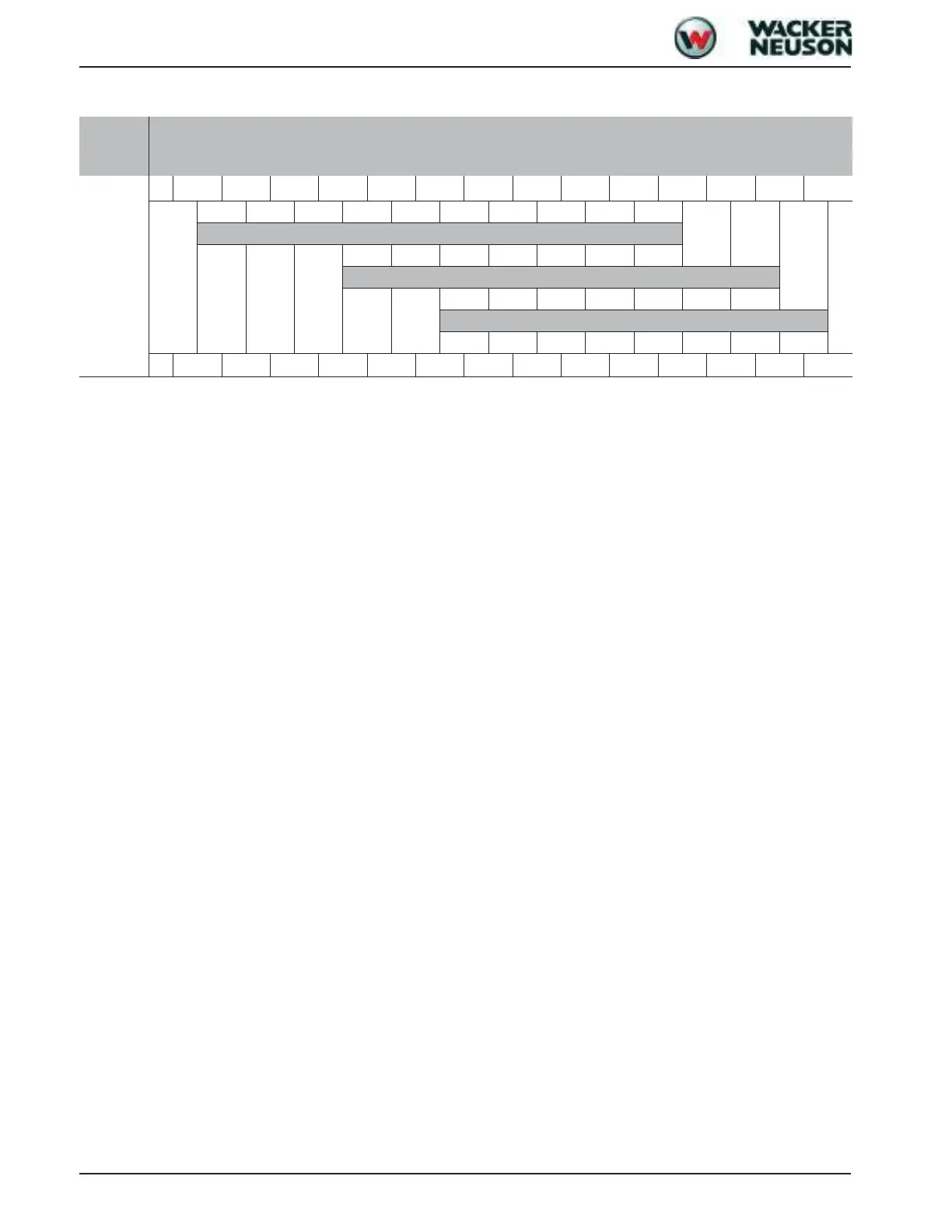
Oil grades for the hydraulic system, depending on temperature
Hydrau-
lics oil
grade
Ambient temperature (C°/°F)
HVLP
1
°C
-20-15-10-5 0 5 1015202530354050
ISO VG32
ISO VG46
ISO VG68
°F
-4 5 14233241505968778695104
122
1. According to DIN 51524 section 3

 Loading...